Two simple timer circuits.
It's assumed that you've read - and understood - the contents of the previous two sections. In this section - we're going to change the configuration of Circuits 1 & 2 - to make them more suitable for longer time delays. In the previous sections - the time delay was produced by a resistor charging a capacitor. In this section - the resistor's job is to discharge the capacitor.
With a very high value timing resistor - a leaky capacitor might prevent the input pins from ever reaching the switching voltage of the gate. This is because the resistor forms a potential divider with the leaking capacitor. Roughly speaking - if more than half of the supply voltage is dropped across the resistor - there won't be enough voltage across the capacitor - to switch the gate.
The problem doesn't arise when the resistor is discharging the capacitor. Here - the timing components are connected in parallel - and not in series. There is no potential divider. If the capacitor is leaking - it's helping the resistor to do its job. The leakage current may limit the maximum length of the delay. But the time period will always end. It doesn't matter how large you make the value of the resistor. Eventually - the capacitor will discharge. And the state of the input pins will change.
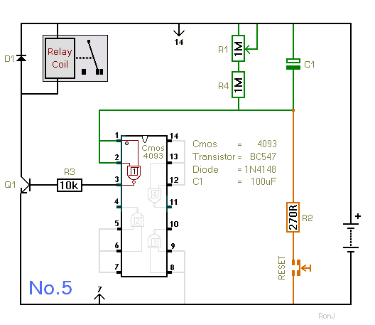
Circuit No.5
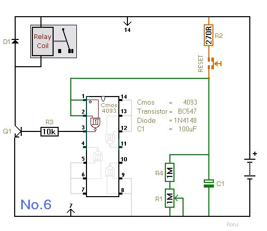
Circuit No.6
 SUGGESTIONS