How to turn a few simple timer circuits - into a practical Intruder Alarm System.
It's assumed that you've read - and understood - the contents of the previous four sections. Here - we're going to use some of the same techniques - to produce a burglar alarm. Don't be put off if the circuit diagram looks a bit complicated. You already know most of it. It's just four simple timers.
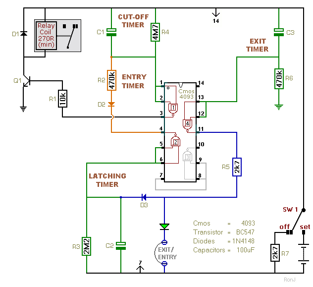
The Exit Timer is first. It allows you to leave the building. This is followed by an Indefinite Pause - while the alarm waits for an intruder. When one of the normally-closed trigger switches is opened - Pin 11 will activate the Latching Timer. It prevents the intruder from defeating the alarm - by simply closing the door behind him. The Latching Timer output starts the Entry Timer. It gives a legitimate visitor time to switch the alarm off. And finally - there's the Cut-Off Timer. It stops the noise from becoming a nuisance.
Circuit No.9
When the alarm is switched off - Sw1 connects R7 across the two supply lines. Because it's only in circuit when the power is off - R7 uses no current. Its purpose is to speed up the discharge of the three timing capacitors. Until the capacitors are completely discharged - the various timers are not completely reset.
Circuit No.10
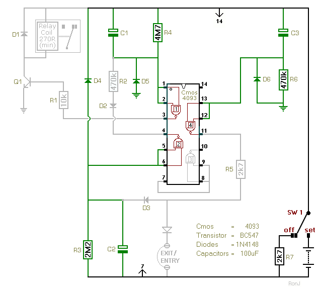
When the alarm is switched off - the existing circuit components will provide a number of more or less satisfactory discharge paths for the three capacitors. And R7 will help - by creating a few more.
In normal use - this uncertainty surrounding the precise discharge routes - probably isn't a problem. But an alarm circuit should really operate reliably and predictably - every time. So we're going to improve the design - by providing a dedicated rapid discharge path - for each capacitor.
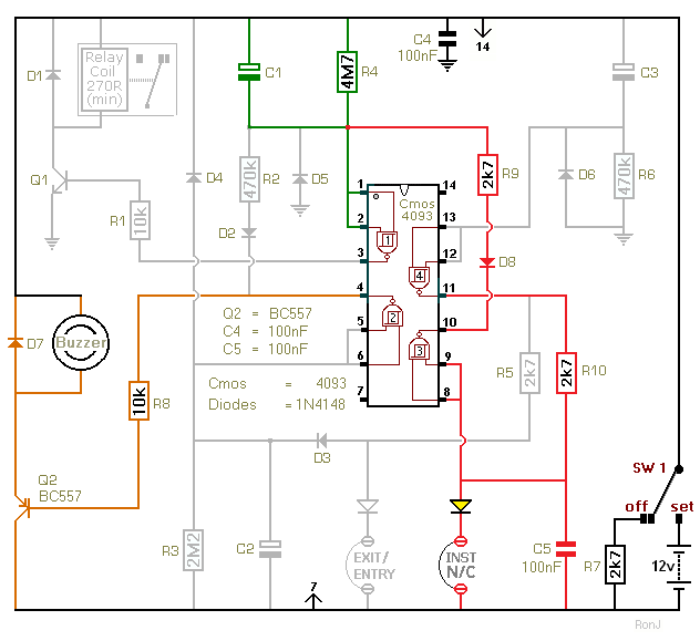
Circuit No.11
There are two further features we can add to our alarm circuit. One is an entry buzzer - and the other is an instant alarm zone. We'll use a second transistor switch to sound the buzzer. And the spare inverter will provide the instant zone. The instant zone will bypass the entry delay - and sound the siren immediately.
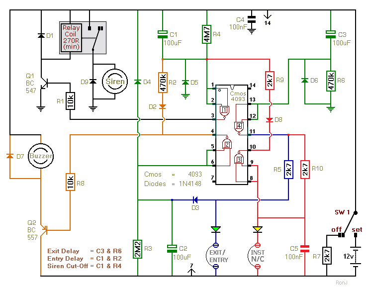
The Complete Two-Zone Alarm Circuit
Click Here For A Photograph Of The Prototype.
This is the complete two-zone alarm circuit. It can be triggered by the usual types of normally-closed input devices - such as magnetic reed contacts - foil tape - PIRs etc. I've used a 12-volt supply in the diagram - but the circuit will work at anything from 9 to 15-volts. All you need do is select a siren, buzzer and relay to suit the voltage you want to use.
About ten minutes after the normally-closed loops have been restored - the siren will switch off - and the alarm will return to standby mode. It can then be re-activated by a subsequent intruder. If you don't want the siren to sound a second time - add the One-Time-Only Module. It forces the siren to switch off after the first ten minutes. And it prevents the alarm from activating a second time. The One-Time Only Module has other uses - so it's worth a look.
Two-Zone-Alarm - Construction Guide
Click Here For A Photograph Of The Prototype.
 SUGGESTIONS