Free Details Of How To Build A General-Purpose Keypad-Operated Door/Safe Lock Release Switch - using cheap off-the-shelf components.
Introduction
The prototype of the Electronic Door Release Circuit was built using only the Stripboard Layout as a guide. So - if you have faithfully reproduced that layout - you will have a working circuit.
Once you're satisfied that your layout is correct - and you have made a careful and thorough check of the underside of the board - it's time to power-up the circuit and test its operation. This is always an anxious moment. If you construct a lot of circuits - you might consider building the
Current Limiting Power Supply - or alternatively - you could add the Simple Current Limiter to your existing PSU. Both will let you set an upper limit on the amount of current supplied to your circuit - and so protect it from any serious damage.
Setup
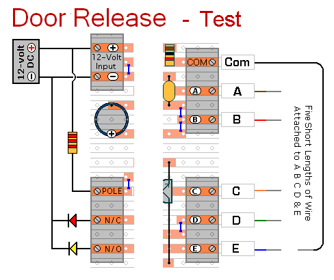
Begin by setting R4 at about mid-point. Then connect five short lengths of wire to the "A B C D & E " terminals - and connect a longer piece of wire to the "Com" terminal. You're going to touch the short wires with it - so it needs to be long enough to reach as far as "E". Strip a little of the insulation from the ends of all six wires.
If You Find a Problem
If - in the course of the test - you find that something is not working properly, then a careful inspection of the relevant area of the circuit board should turn up the cause of the problem. Where you've cut the board to size - look for small loose strands of copper left behind by the saw. Check the board for short-circuits caused by component leads touching each other. If an LED is not lighting - check that it's connected the right way round. It can also happen that the stripboard itself is faulty. I have seen cases where the copper tracks have not been completely severed from one another during manufacture.
If you've built your circuit using the specified components - and you've followed the step-by-step construction guide described on the Support Page - then the chances are that any bug will be caused by something minor - a component connected the wrong way round - a missing or unwanted solder bridge - an incomplete cut in the track etc. If you haven't used the specified transistors - check the pin configuration. Just because the transistors look the same - do not assume that they have the same pin configuration.
If you can't see anything obvious then adopt a systematic approach to faultfinding. Simply replacing components at random is rarely successful. Begin by double-checking that all of the cuts in the tracks have been made - that they are all In The Right Place - and that they sever the track completely. Use a magnifying glass - and backlight the board. It only takes the smallest strand of copper to cause a problem.
When you're satisfied that the tracks have been severed in all the right places, check that you have made - and correctly placed - all 6 solder bridges. Check especially the bridge that connects pins 7 of the IC to the track below. Mark each bridge with a felt tip pen - or something similar - so that it can be easily identified later.
Next, carefully examine the full length of each track. If you backlight the board - it makes potential problem areas easier to spot. Look for unwanted solder bridges. Your felt tip markings will tell you which ones should be there - and help you identify any that shouldn't be there.
If all else fails and you still haven't found the cause of the problem - work your way through the assembly instructions on the Support Page. Check each individual component and link - to make sure that it's present and correctly positioned. Make sure that Pin 1 of the IC is in the top left-hand corner - and that all of its pins are correctly inserted into the socket. Take your time and examine each individual component carefully.
Print out the drawings and mark off the components as you go. Pay particular attention to the orientation of the diodes, the transistors and the electrolytic capacitors. Electrolytic capacitors generally have a light coloured stripe down the side next to the negative terminal. Note that all three electrolytic capacitors are mounted with their negative terminals facing the top of the board. See The Photograph Of The Prototype
Alternatively, you can take the following approach - suggested for those who have not used the stripboard layout.
If You Have Designed Your Own Layout
For faultfinding purposes you can think of the circuit in two distinct halves. There is the code input section that results in pin 4 going high - and the output section that causes the relay to energize and de-energize.
Try to get the output section working first. Start by disconnecting the end of R8 that goes to pin 4.
Turn-on the power and touch the "Common" wire to the free end of R8. The relay should energize. Next, take the wire away from R8. The relay should de-energize. In other words - by touching R8 with the "Common" lead - you should be able to energize the relay.
Once you have your relay operating properly - reconnect R8 to pin 4. Then check to see if your circuit is working. If it's not - examine the code entry section.
Disconnect one side of R3 to defeat the automatic reset. Then turn-on the power and - using a digital voltmeter - go through the code entry sequence and make the following checks. If at any stage you do not get the correct reading - investigate.
- Touch "E" briefly with the "Common" lead - and check that this takes pin 1 low.
- Next check that pin 1 is high - that pin 2 is low - and that pin 3 is low.
- Touch "A" briefly with the "Common" lead. Check that this takes pin 2 high - and that it stays high.
- Check that pin 3 is now high. This means that gate 1 has functioned properly.
- Check that pin 12 is high, that pin 11 is low and that pin 13 is low.
- Touch "B" briefly with the "Common" lead. Check that this takes pin 13 high - and that it stays high.
- Check that pin 11 is now high. This means that gate 2 has functioned properly.
- Check that pin 8 is high, that pin 9 is low and that pin 10 is low.
- Touch "C" briefly with the "Common" lead. Check that this takes pin 9 high - and that it stays high.
- Check that pin 10 is now high. This means that gate 3 has functioned properly.
- Check that pin 5 is high, that pin 6 is low and that pin 4 is low.
- Touch "D" briefly with the "Common" lead. Check that this takes pin 6 high - and that it stays high.
- Check that pin 4 is now high. This means that gate 4 has functioned properly.
- Check that pin 4 goes low after about 30-seconds. This means that C4 has discharged.
If pin 4 goes high - and it remains high for about 30-seconds - the code entry sequence has been successful. Now that you have both the input and output sections working - reconnect R3 and check that your circuit is functioning correctly - by using the procedure described at the Top of the Page .
 SUGGESTIONS