The adjustable hysteresis allows you to select the size of the difference between the temperature at which the relay will energize - and the temperature at which it will de-energize.
COMMENTS Homer SUGGESTIONS

Thermostat With Hysteresis - Support Material

MORE CMOS CIRCUITS

Thermostat
Front Page
The Rest of Ron's Circuits Write To Ron More Free-to-Use Circuits Circuit Exchange International


By changing the values of R1, R2 & R3 - you can select both the temperature range available - and the amount of hysteresis. Component tolerances make it difficult to predict the precise results any set of resistor values will give. But the Accompanying Spreadsheet should help you choose the right value resistors for your application.

Circuit Description

Click Here For A Photograph Of The Prototype.

Circuit Diagram For A 
Temperature Controlled Relay
Learn More About Cmos Inverters


Parts List

Parts List

Suppliers


Worldwide
RS Components


UK & Ireland
Maplin


Construction Guide

Click here if you're new to constructing stripboard projects.

The terminals are a good set of reference points. To fit them - you may need to enlarge the holes slightly. Then turn the board over and use a felt-tip pen to mark the 19 places where the tracks are to be cut. Before you cut the tracks - use the "actual size" drawing to Check That The Pattern is Correctly Marked .


Thermostat With Hysteresis
Pattern For Cutting The Tracks


Actual Size


Stripboard 
    - Actual Size -


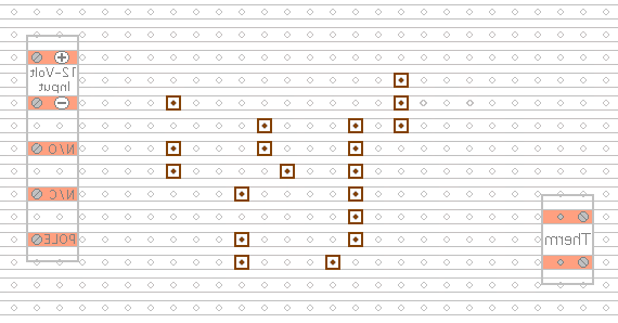
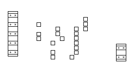
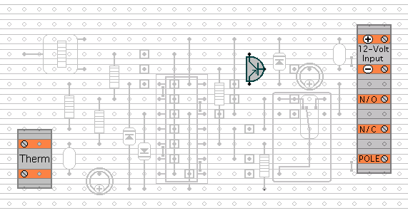
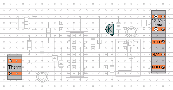
When you're satisfied that the pattern is right - cut the tracks. If you don't have the proper track-cutting tool - then a 6 to 8mm drill-bit will do. Just use the drill-bit as a hand tool - there's no need for a drilling machine. Make sure that the copper strip is cut all the way through. Sometimes a small strand of copper remains at the side of the cut and this will cause malfunction. Use a magnifying glass - and backlight the board. It only takes the smallest strand of copper to cause a problem.
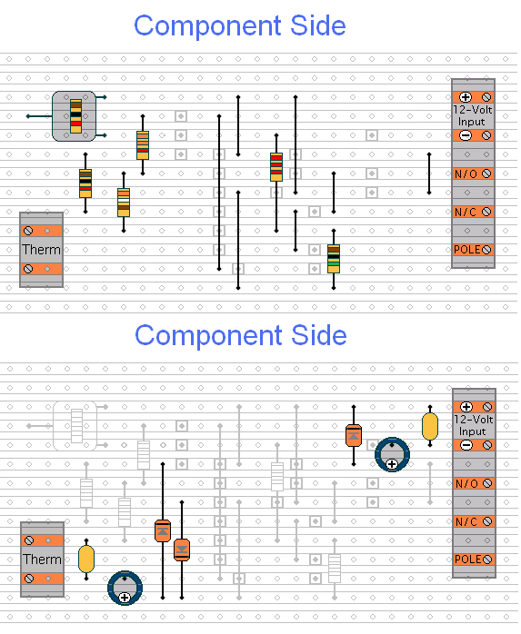
Next - fit the Seven Wire Links - the preset - and the five fixed resistors. For the links - I used bare copper wire on the component side of the board. Telephone cable is suitable - the single stranded variety used indoors to wire telephone sockets. Stretching the core slightly will straighten it - and also allow the insulation to slip off.


Thermostat With Hysteresis - Make A


Next - fit the three diodes and the fours capacitors. Pay particular attention to the orientation of both the diodes and the electrolytic capacitors. See the Photograph Of The Prototype. Then - fit the relay and the IC socket.


Thermostat With Adjustable Hysteresis - Make B


Turn the board over and examine the underside carefully - to make sure that there are no unwanted solder bridges or other connections between the tracks. If you backlight the board during the examination - it makes potential problem areas easier to spot. When you're satisfied that everything is in order - add the 6 solder bridges.

Fit The Transistor

If you want the relay to energize when the temperature falls below the preset level - you should use a BC557. If you want the relay to energize when the temperature rises above the preset level you should use a BC547. Note that the transistors face in opposite directions. The BC557 faces left. And the BC547 faces right.


BC557 PNP

BC557


BC547 NPN

BC547

Finish off by inserting the Cmos IC into the socket. Pin 1 of the IC should be in the top left-hand corner. Check that all 14 pins have entered the socket. Sometimes - instead of entering the socket - a pin will curl up under the IC.


You Are Now Ready To Test Your Finished Circuit Board.

Schematic
Diagram
The Rest of Ron's Circuits Write To Ron More Free-to-Use Circuits Circuit Exchange International


Free Web Hosting