This is a free circuit diagram for an electronic thermostat with adjustable hysteresis.
A thermostat doesn't try to maintain a constant temperature. In order to do so - it would have to keep switching on and off every few seconds. Instead - it keeps the temperature within a specific range. When the preset temperature has been reached - it switches off. And it only switches on again - when there has been a significant change in temperature.
The difference between the temperature at which the thermostat switches off - and the temperature at which it switches on again - is the hysteresis. Without this hysteresis - your central heating, refrigerator etc. would keep switching on and off every few seconds.
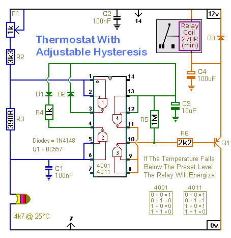
This particular circuit energizes the relay when the temperature falls - and de-energizes the relay when the temperature rises again. If you replace the pnp transistor (BC557) with an npn transistor (BC547) - the circuit will operate the other way round.
In order to minimize power consumption - choose the configuration that energizes the relay for the shorter time period. If it's going to be hot most of the time - choose the one that energizes the relay when the temperature falls (BC557). If it's going to be cold most of the time - choose the one that energizes the relay when the temperature rises (BC547).
Circuit Diagram
Click Here For A Photograph Of The Prototype
Temperature Range
There are many factors that influence how a thermostat will perform. For example - heat energy stored in a heater may go on raising the temperature - even after the heater has switched off. Similarly - even after the heater has switched on again - the temperature may continue to fall - while the cold heater warms itself up. In other words - the system you're trying to control - may have some hysteresis of its own.
The temperature at which the relay will energize - is controlled by the voltage on pins 5 & 6. And the temperature at which the relay will de-energize - is controlled by the voltage on pins 1 & 2. The difference between the two temperatures - the hysteresis - is controlled by the value of R3.
With the component values used in the prototype - the temperature at which the relay energizes can be adjusted - from roughly 22şC (ş72F) to 29şC (84şF). And the hysteresis is around 4şC (7şF). Because of manufacturing tolerances - your results are likely to be different. But - by changing the values of R1, R2 & R3 - you can select both the temperature range available - and the amount of hysteresis.
The value of R1 sets the width of adjustment available. The higher the value of R1 - the wider the range of possible temperature settings. However - if you make the range of adjustment too wide - setting a precise temperature becomes more difficult. A lower value pot - or a multi-turn pot - will make fine adjustment much easier. Turning R1 to the right increases the temperature setting. And turning R1 to the left reduces the temperature setting.
R2 lets you choose the area of the temperature scale in which the thermostat is to operate. Reducing the value of R2 gives access to higher temperatures. Increasing the value of R2 gives access to lower temperatures. Use R2 to take you close to your target temperature - and use R1 to provide the fine adjustment.
R3 controls the amount of hysteresis. Increasing the value of R3 increases the hysteresis - and decreasing the value of R3 reduces the hysteresis. The actual amount of hysteresis provided by any given value resistor - depends on the area of the temperature scale you've selected. The resistance required - per degree of hysteresis - is higher at low temperatures - and lower at high temperatures.
Component tolerances make it difficult to predict the precise results any set of resistor values will give. However, the Support Material for this circuit includes a spreadsheet that will Help You Choose the right value resistors for your application. It also includes a parts list - a step-by-step guide to the construction of the circuit board - a detailed circuit description - and more.
 Do not use the "on-board" relay to switch mains voltage. The board's layout does not offer sufficient isolation between the relay contacts and the low-voltage components. If you want to switch mains voltage - mount a suitably rated relay somewhere safe - Away From The Board. Alternatively - you may be able to drive the mains device directly - via an Optical Isolator
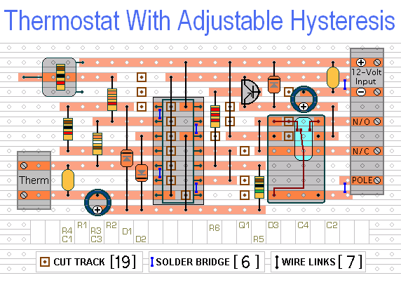
Veroboard Layout
Click Here For A Photograph Of The Prototype
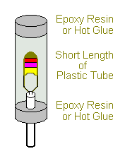
The Temperature Sensor
The mass of the thermistor is small - and it will react quickly to changes in temperature. This makes it sensitive to thermal currents. One solution is to create an enclosed environment - where the thermistor is protected from momentary draughts - but can still respond to slower changes in the overall ambient temperature. Another solution is to increase its mass - by attaching it to a small metal heatsink.
Setting the operating temperature is best carried out "in situ" using trial-and-error. If the relay reacts at too low a temperature - turn R1 a little to the right. If it reacts at too high a temperature - turn R1 a little to the left. If you use a multi-turn pot - you can make very fine adjustments.
You'll want the thermistor to respond to changes in the temperature of whatever substance you're monitoring - air, liquid, etc. So make sure that the sensor is receiving its heat from that substance - and not directly from the heat source. Simple example - if you wanted to monitor the air temperature in a room - you wouldn't place the sensor next to the radiator.
The Supply Voltage
The circuit is designed for a 12-volt power supply. However - it will work at anything from 5 to 15-volts. All you need do is select a relay with a coil voltage that suits your supply. And make sure that the coil doesn't draw more than about 50mA - otherwise the transistor might be overloaded. I've used a single-pole relay in the diagrams - but you can use a multi-pole relay if it suits your application. The Support Material for this circuit includes a parts list - a step-by-step guide to the construction of the circuit board - a detailed circuit description - and more.
Alternative Optical-Isolator Output
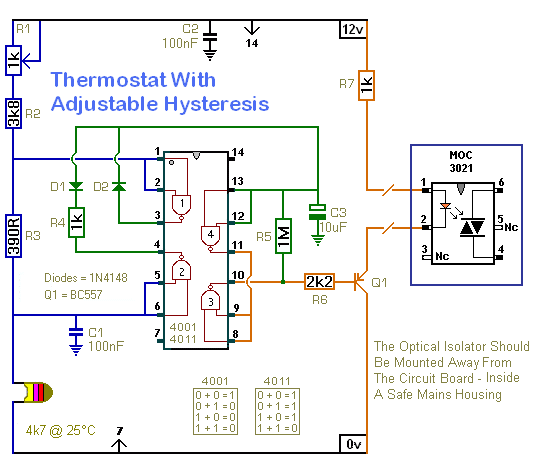
If you intend to use the circuit to control mains devices - the relay can be replaced by a whole range of optical-isolators - such as the MOC 3021. Please note that I am unable to help with the selection of suitable types of isolator - and I cannot supply circuit diagrams or connection details.
 SUGGESTIONS
