By changing the values of R1, R2 & R3 - the
Thermostat Circuit can be adapted to operate in different areas of the temperature scale - and to provide different amounts of hysteresis.
R1 is the variable resistor. Its value determines the width of adjustment available. The greater the value of R1 - the wider the range of temperatures that may be set. However - if you make the value of R1 too high - the control will become coarse. And it will be more difficult to make precise adjustments to the temperature setting.
R2 is a fixed resistor. Its value determines the area of the temperature scale in which the thermostat will operate. The higher the value of R2 - the lower the temperatures at which the relay will activate - and vice-versa. Use R2 to take you close to your target temperature - and use R1 to provide the fine adjustment.
R3 is also a fixed resistor. Its value determines the amount of hysteresis provided by the thermostat. That is - it fixes the size of the difference - between the temperature at which the relay will energize - and the temperature at which the relay will de-energize.
Unfortunately - these three resistors do not operate entirely independently of one another. And matters are further complicated by the influences of the supply voltage - the switching voltage of the Cmos gates - and the manufacturing tolerances of the thermistor. The marked value of the thermistor can be out by as much as ± 20%.
The
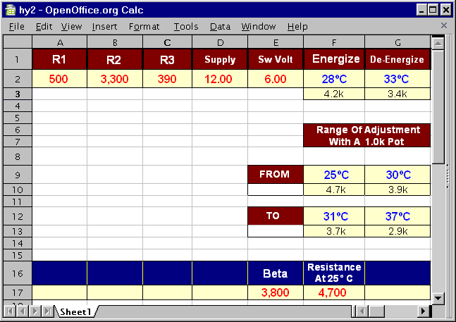
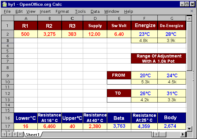
Zip File contains both OpenOffice and MS Works spreadsheets. Two versions of each type are available. The first - and simpler to use - spreadsheet relies on the thermistor's marked value - and the typical figure for Beta given in the datasheets. It will let you play about with the resistor values - and the supply and switching voltages. It won't be very accurate. But it will illustrate the principles involved. And - together with a little trial and error - it should help you set up your circuit.
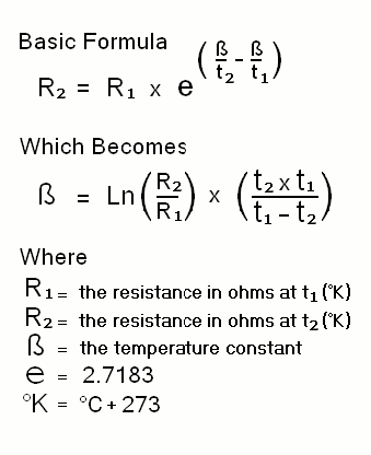
The second spreadsheet requires much more accurate input data. You'll need to
Measure The Switching Voltage of your Cmos gates. You'll also need two accurate resistance measurements - taken from your thermistor - at two different temperatures. Before using the second spreadsheet - take a look at the
Thermistor Guide. It explains how you can get some real and reliable data from your thermistor.
 SUGGESTIONS
 SUGGESTIONS


