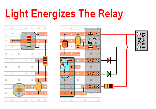
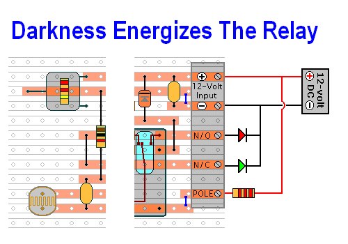
Two LDR circuits that will energize a relay at dusk or at dawn.

Do not use the "on-board" relay to switch mains voltage. The board's layout does not offer sufficient isolation between the relay contacts and the low-voltage components. If you want to switch mains voltage - mount a suitably rated relay somewhere safe -Away From The Board.
Introduction
The prototypes of the two LDR circuits were built using only the Stripboard Layout as a guide. So - if you have faithfully reproduced the layout - you will have a working circuit.
Once you're satisfied that your layout is correct - and you have made a careful and thorough check of the underside of the board - it's time to power-up the circuit and test its operation. This is always an anxious moment. If you construct a lot of circuits - you might consider building the Current Limiting Power Supply - or alternatively - you could add the Simple Current Limiter to your existing PSU. Both will let you set an upper limit on the amount of current supplied to your circuit - and so protect it from any serious damage.
Light Energized Relay - Test
Click Here For A Photograph Of The Prototype
Dark Energized Relay - Test
Click Here For A Photograph Of The Prototype
|
|
If You Find a Problem
If - in the course of the test - you find that something is not working properly - then a careful inspection of the relevant area of the circuit board should turn up the cause of the problem. Where you've cut the board to size - look for small loose strands of copper left behind by the saw. Check the board for short-circuits caused by component leads touching each other. If an LED is not lighting - check that it's connected the right way round. It can also happen that the stripboard itself is faulty. I have seen cases where the copper tracks have not been completely severed from one another during manufacture.
If you've built your circuit using the specified components - and you've followed the step-by-step construction guide described on the Support Page - then the chances are that any bug will be caused by something minor - a component connected the wrong way round - a missing or unwanted solder bridge - an incomplete cut in the track etc.
If you can't see anything obvious then adopt a systematic approach to faultfinding. Begin by double-checking that all of the cuts in the tracks have been made, that they are all - In The Right Place - and that they sever the track completely. Use a magnifying glass. It only takes the smallest strand of copper to cause a problem. If you backlight the board during the examination - it makes them easier to spot.
When you're satisfied that the tracks have been severed in all the right places, check that you have made - and correctly placed - all of the solder bridges. Mark each bridge with a felt-tip pen - or something similar - so that it can be easily identified later.
Next - carefully examine the full length of each track. Look for unwanted solder bridges. Your felt-tip markings will tell you which ones should be there - and help you identify any that shouldn't be there. Again, if you backlight the board during the examination - it makes potential problem areas easier to spot.
If all else fails and you still haven't found the cause of the problem - work your way through the assembly instructions on the Support Page. Check each individual component and link - to make sure that it's present and correctly positioned.
Print out the drawings and mark off the components as you go. Pay particular attention to the orientation of the diode and the transistor. Take your time and examine each individual component carefully.
 SUGGESTIONS