The prototype of the Inertia Sensor Module was built using only the Stripboard Layout as a guide. So - if you have faithfully reproduced that layout - you will have a working circuit.
Once you're satisfied that your layout is correct - and you have made a careful and thorough check of the underside of the board - it's time to power-up the circuit and test its operation. This is always an anxious moment. If you construct a lot of circuits - you might consider building the
Current Limiting Power Supply - or alternatively - you could add the
Simple Current Limiter to your existing PSU. Both will let you set an upper limit on the amount of current supplied to your circuit - and so protect it from any serious damage.
Setup
You can simulate the trigger-switch using two short lengths of flexible multi-stranded wire - such as alarm cable. But if you want to check the sensitivity adjustment - you'll have to connect an inertia-sensor to the input terminals. An LED is all that's needed to demonstrate that the output is working properly.
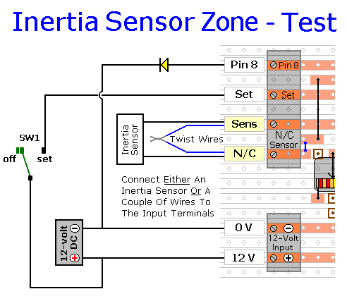
Connect an LED between the "Pin 8" output and the negative line. There is no need to use a series resistor. The job of limiting the output current is done by RS9. I used a Yellow LED in the diagram because - in what follows - I wanted to be able to distinguish between it and the other LEDs on the circuit board. You can use whatever colour you have available.
Even if you're using inertia sensors - start by connecting two short lengths of wire to the normally-closed input terminals. Strip the insulation from the ends of the wires - and twist them together to simulate a normally-closed loop.
Next, connect the on/off switch - SW1. Then place the switch in the "Off" position - and leave it there.
Finally, connect the 12-volts DC to the input terminals. Pay particular attention to the polarity of the supply. Note that the positive connection goes to the bottom terminal.
Turn On The Power
At this stage the green LED should be lighting - and the Red LED should be off. While SW1 in the "Off" position - we want the green LED to react to the input. But we don't want the red LED to record that input as an alarm activation.
Open and close the wire loop a few times. As you do so, the green LED should turn off and on. But the red LED should not light. When you're satisfied that it's working properly - twist the two wires back together.
Next - turn VS1 all the way to the left. Then move SW1 to the "Set" position. When you open the loop - both the yellow LED and the red LED should light. Close the loop again. After a couple of seconds, the yellow LED should turn off - but the red LED should remain lit. Open and close the loop a few more times. Each time - the yellow LED should turn off after a couple of seconds - but the red LED should remain lit. Next, move SW1 to the "Off" position. The red LED should remain lit - to indicate that the zone has caused an alarm activation. When you're ready - press the reset button - and the red LED should turn off.
If you are using an inertia sensor - it should be mounted on something solid - or clamped in a vice. Discard the wire loop - and replace it with the leads from the sensor. Turn VS1 all the way to the right - its most sensitive position. Then move SW1 to the "Set" position. Tap the sensor with the handle of a screwdriver. A relatively gentle tap should be sufficient to turn on both the yellow and the red LEDs. After a couple of seconds - the yellow LED should turn off - but the red LED should remain lit.
Repeat the test a number of times. Each time - turn VS1 a little bit more to the left - and wait a few seconds for CS2 to discharge. You should find that you need progressively harder blows to make the yellow LED light. If your blow is not hard enough then - before you tap the sensor again - wait a few seconds for CS2 to discharge. This will give you the most accurate impression of the strength of blow needed for each setting of VS1.
You should also find that - as well as reacting to a single heavy blow - a series of gentler blows will also produce an output. Provided the delay between the blows is short - they will progressively charge CS2 to the point where the module reacts. Thus, a low level - but sustained - attempt to force entry, will also activate the alarm.
Finally, move SW1 to the "Off" position. The red LED should remain lit - to indicate that the zone has caused an alarm activation. When you're ready, press the reset button - and the red LED should turn off.
If You Find a Problem
If - in the course of the test - you find that something is not working properly, then a careful inspection of the relevant area of the circuit board should turn up the cause of the problem. If an LED is not lighting - check that it's connected the right way round.
Where you've cut the board to size - look for small loose strands of copper left behind by the saw. Check the board for short-circuits caused by component leads touching each other. It can also happen that the stripboard itself is faulty. I have seen cases where the copper tracks have not been completely severed from one another during manufacture.
If you've built your circuit using the specified components - and you've followed the step-by-step construction guide described on the
Inertia Sensor Module - Support Page - then the chances are that any bug will be caused by something minor - a component connected the wrong way round - a missing or unwanted solder bridge - an incomplete cut in the track etc.
If you can't see anything obvious - then adopt a systematic approach to faultfinding. Begin by double-checking that all of the cuts in the tracks have been made, that they are all -
In The Right Place - and that they sever the track completely. Use a magnifying glass. It only takes the smallest strand of copper to cause a problem.
When you're satisfied that the tracks have been severed in all the right places, check that you have made - and correctly placed - all 8 solder bridges. Check especially the bridge that connects pin 14 of the IC to the positive line. Mark each bridge with a felt tip-pen - or something similar - so that it can be easily identified later.
Next, carefully examine the full length of each track. Look for unwanted solder bridges. Your felt-tip markings will tell you which ones should be there - and help you identify any that shouldn't be there.
If all else fails - and you still haven't found the cause of the problem - work your way through the assembly instructions on the
Support Page. Check each individual component and link - to make sure that it's present and correctly positioned.
Print out the drawings and mark off the components as you go. Pay particular attention to the orientation of the diodes and the electrolytic capacitor. Make sure that Pin 1 of the IC is in the top left-hand corner - and that all of its pins are correctly inserted into the socket. Take your time and examine each individual component carefully.
 SUGGESTIONS
