Circuit Description:-
This module allows you to use Inertia (Shock) Sensors with the
Modular Burglar Alarm circuit. Although it's intended primarily for Inertia Sensors - a mixture of Sensors and Magnetic Reed Contacts etc. - may be included in the normally-closed loop.
Inertia Sensors are devices that react to vibrations. They do not react to constant low level vibrations of the sort you would get from loud music or heavy road traffic. Instead they have a certain amount of inertia that must be overcome before they react. In other words - they need a sharp blow - such as would be required to break a pane of glass.
Essentially - they are small normally-closed switches - the contacts of which are joined by a specially weighted bar. It's the weights on the bar that provide the inertia. When a blow is struck - the bar bounces - and the circuit opens briefly. The length of time the switch is open depends on the strength of the blow - i.e. how high the bar bounces.
The alarm circuit sensitivity is adjusted by altering the speed at which it reacts - i.e. the speed at which CS2 charges through VS1.
The circuit uses a Cmos 4081 - four two-input AND gates. These gates only produce a high output when BOTH inputs are high. The circuit is permanently connected to the 12-volt supply. When the alarm is 'Off ' - RS2 holds pin 2 low - so there can be no output from Gate 1. Therefore, the Module is inactive. When the alarm is "Set" - SW1 takes Pin 2 high - and the Module is enabled.
Now - if the sensor loop is opened - RS1 will take pin 1 high - and an output will appear at pin 3. It is the job of pin 3 to charge CS2 - and so take pins 5 and 6 high. How quickly it does this depends on the setting of VS1.
If VS1 is set at a low value - CS2 will charge very quickly. This means that a light tap on the sensor will activate the alarm. However - if VS1 is set at a high value - a heavy blow will be required. DS1 allows CS2 to charge through VS1- but prevents CS2 from discharging back through VS1. Instead - RS3 provides a slow discharge path for CS2. There are three reasons for using this configuration.
Firstly - RS3 lengthens the period of time during which CS2 holds pins 5 and 6 high. So the length of the output pulse at pin 4 is not dependant on the sensitivity setting of VS1 - or the strength of the blow.
Secondly - following an activation - when the trigger circuit is restored - RS3 ensures that CS2 will discharge and the zone will reset.
Thirdly - although a very light blow may not activate the alarm - it would still put a certain amount of charge into CS2. Over time - a number of light insignificant blows would charge CS2 to the point where the alarm activates. By constantly discharging CS2 - RS3 ensures that this can't happen.
When CS2 takes pins 5 and 6 high - the output at pin 4 will go high. The output will only be a short pulse. To lengthen this pulse - CS4 charges rapidly through RS4 - and is then prevented from discharging back through RS4 - by DS3. Instead - CS4 discharges slowly through RS5. This means that pins 8 and 9 will be held high for a few seconds.
During this time, the output from pin 10 will be high. This will take "A" high and activate the Modular Alarm's instant zone. RS9 limits the current surge as the output of gate 3 charges C5 on the main circuit board - and DS5 prevents any current returning to pin 10 from the main alarm circuit. This allows several different Modules to be connected to "A" - without their interfering with each other.
The output at pin 10 has another job to do. It takes pins 12 and 13 high through RS8. The diode - DS4 - allows pin 10 to take the inputs high - but prevents it from taking them low again.
When the inputs at pins 12 and 13 go high - the output at pin 11 goes high also. Gate 4 then latches itself on by taking its own inputs high through RS6. It also lights the Red LED through RS7. The LED indicates that the alarm circuit connected to this module has been activated. This is invaluable where you have several Zones. It will tell you immediately where the intruder has attempted to gain entry - or if you are suffering from "false alarms" - which Zone is giving trouble.
The Reset button takes pins 12 and 13 low. The output at Pin 11 goes low - and the LED switches off. Note that the button only turns off the LED. It does NOT reset the zone. The zone resets itself automatically when the trigger circuit is restored - and this happens regardless of whether or not the LED is lighting. DS6 allows several Modules to be connected to the same Reset button without their interfering with each other.
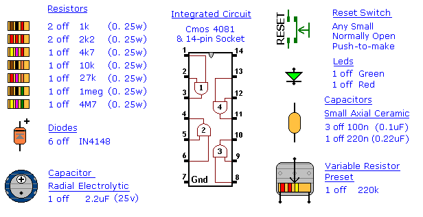
Inertia Sensor Module - Parts
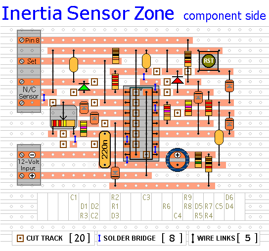
Inertia Sensor Layout
Inertia Sensor Module - Construction Guide
Click here if you're new to constructing stripboard projects.
The prototype of the Inertia Sensor Module was built using only the Stripboard Layout as a guide. So - if you reproduce that layout - you will have a working circuit. Details of how to
Test Your Finished Circuit Board are also provided.
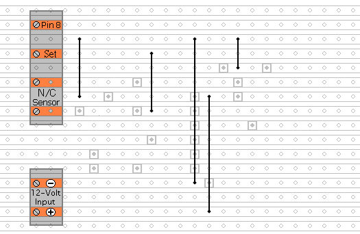
The terminals are a good set of reference points. To fit them, you may need to enlarge the holes slightly. Then turn the board over and use a felt-tip pen to mark the 20 places where the tracks are to be cut. Before you cut the tracks, use the "actual size" drawing to
Check That The Pattern is Correctly Marked .
When you're satisfied that the pattern is right - cut the tracks. Make sure that the copper is cut all the way through. Sometimes a small strand of copper remains at the side of the cut and this will cause malfunction. Use a magnifying glass. It only takes the smallest strand of copper to cause a problem. If you don't have the proper track-cutting tool, then a 6 to 8mm drill-bit will do. Just use the drill-bit as a hand tool - there's no need for a drilling machine.
Cut the Tracks
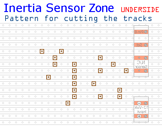
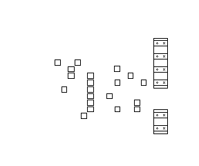
Actual Size Of Pattern
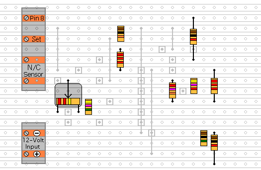
Fit The Five Wire Links
Next make and fit the Five Wire Links. I used bare copper wire on the component side of the board. Telephone cable is suitable; the single stranded variety used indoors to wire telephone sockets. Stretching the core slightly will straighten it; and also allow the insulation to slip off.
Fit The Resistors And The Preset
Next fit the 9 resistors and the preset. The resistors are all shown lying flat on the board. But those connected between close or adjacent tracks are mounted standing upright.
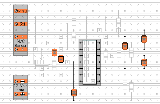
Fit The Diodes And The IC Socket
Again, the diodes are all shown lying flat on the board - but those connected between close or adjacent tracks are mounted standing upright.
Fit The Remaining Components
The Capacitors, The LEDs and The Reset Button.
You'll want to mount the LEDs where they can be seen - perhaps on the front of your alarm-panel. They should be connected to the circuit board using a light flexible wire - e.g. the cores from a piece of alarm cable. They may be attached to the circuit board from the front or the rear. Make them long to begin with. You can shorten them later when you assemble your alarm-panel. Twist the wires into pairs to keep them tidy. Use a similar approach when installing the Reset Button. Any number of expansion modules may be connected to a single Reset Button.
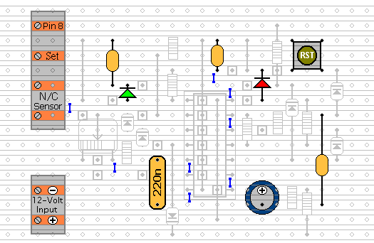
After adding the 8 solder bridges to the underside of the board - examine it carefully - to make sure that there are no unwanted solder bridges or other connections between the tracks. Finally, insert the 4081 into the socket. Make sure that pin 1 is in the top left-hand corner - and check carefully that all of the pins are correctly inserted into the socket. Sometimes - instead of entering the socket - a pin will curl up underneath the IC. You're ready now to
Test Your Finished Circuit Board.
 SUGGESTIONS
