Circuit Description:
The Cmos 4001 is used to provide two
Monostables. Gates 1 & 2 - together with R5 & C3 - form the exit/entry monostable. Gates 3 & 4 - together with V3 & C6 - form the bell monostable. While Sw1 is in the ''off'' position - it holds pins 2 & 13 high - and this prevents the two monostables from triggering.
Pin 6 is the trigger that activates the exit/entry monostable. Depending on the setting of V1 - when SW1 is moved to the "set" position - C2 will continue to keep pin 2 high for up to about a minute. During this time - the pin 6 trigger will not work. Therefore, you can open the exit/entry loop and leave the building.
During the exit delay - when you open the door to leave the building - current through R1 & Z1 will switch Q1 ''on'' and sound the buzzer. When you close the door behind you, the buzzer should stop. This confirms that the exit/entry loop has closed properly within the time allowed. The 9v1 zener is used to prevent the base-emitter junction of Q1 from holding pin 6 permanently low.
While the alarm is off - if V1 is accidentally adjusted to zero ohms - R4 prevents it from causing a short-circuit. R2 & Led 2 provide an indicator that lights when the alarm is "set".
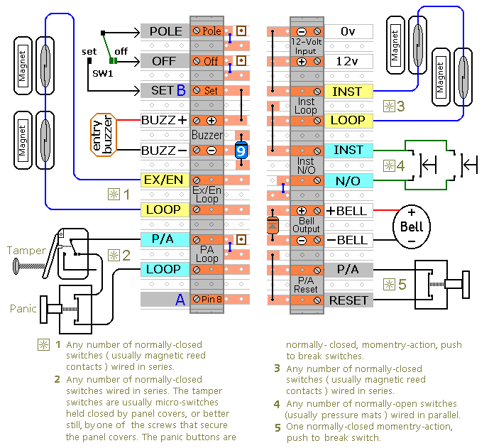
The buzzer is a small ''piezo'' type. It should only take a few milliamps. With such a small buzzer - D1 is probably unnecessary - but its presence means that you are free to connect a small relay to the buzzer output. Such a relay may then be used to turn an ''instant zone'' into an ''access zone'' - or to switch on a light when you enter the building. The total load placed on the buzzer output by the buzzer and relay coil should not exceed about 50mA.
An ''access zone'' is an ''instant zone'' that will allow you to pass - provided you have first entered the building through the ''exit/entry zone''. To turn an ''instant zone'' into an ''access zone'' - connect the coil of a suitable relay to the buzzer output. Then use the relay contacts to disable the ''instant zone'' - while the buzzer is sounding.
After the exit delay - pin 2 is low - and the exit/entry monostable is enabled. When the door is opened - R1 will take pin 6 high - and the exit/entry monostable will trigger. This produces an output at pin 3 - for a period of time set by C3 & R5 - about 3 minutes.
During this time - current through R3 will switch Q1 on - and the buzzer will sound. At the same time - current through V2 will begin to charge C5. This is the entry delay. It can last up to about a minute - depending on the setting of V2. You will generally switch the alarm off during this period.
If you fail to do so - C5 will eventually take pin 8 high. When pin 8 goes high - the bell monostable will trigger. This produces an output at pin 11 - for a period of time set by V3 & C6 - up to about 40 minutes. During this time - current through R9 will turn Q3 on - the relay will energize - and the bell will ring.
The bell monostable only works while pin 13 is low. Moving SW1 to the 'off' position takes pin 13 high - and stops the bell from ringing.
R6 & D2 provide a rapid discharge path for C5. So the entry delay will reset more quickly than it would if C5 had to discharge through V2 alone.
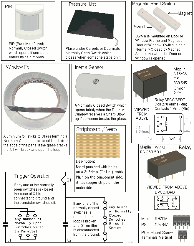
If any switch in the normally-closed "instant" Loop is opened - C5 will charge rapidly through R7 & D3. Pin 8 will go high - trigger the bell monostable - and the bell will ring immediately.
In the same way - if a normally-open switch takes the base of Q2 to ground - the transistor will switch off. This will allow C5 to charge rapidly through R7 & D3. Pin 8 will go high - the bell monostable will trigger - and the bell will ring immediately.
If you do not want to use normally-open switches - leave out R8, C8 and Q2 - and fit a link between Led 3 and C7. If you are building a multi-zone alarm - using the expansion modules - then you may leave out R7, D3, Led 3 and C7 as well.
The PERSONAL ATTACK/TAMPER zone operates 24 hours a day. It will work even when the alarm is ''off''. If the PA/TAMPER loop is opened - current through R11 will trigger the gate of the SCR - and the Bell will ring.
If the SCR is to latch ''on'' - then it must have a constant minimum current flowing through it. R10 provides this current. Whether or not R10 is necessary depends on the type of sounder you use. If you are using an electronic siren - you probably don't need R10. However, a bell has a built-in switch that interrupts the current as it rings - so R10 is necessary to supply current during these interruptions.
To reset the PA/TAMPER zone after activation - first restore the normally-closed loop - and then temporarily interrupt the current flow by pressing SW2. This will unlatch the SCR - and the bell will stop ringing.
If you don't want to use the PA/TAMPER feature - simply leave out R10, R11, C9, SW2 and the SCR.
The wires that go to the switches on the doors and windows - can act like a radio antenna. They pick up stray signals that can cause ''false alarms''. C1, C7, C8, & C9 are there to de-tune the various circuits. Note that the gate of the SCR is much more sensitive than the other circuits - because it triggers at a much lower voltage. That's why C9 is much larger than the other capacitors.
Relay coils and some sounders produce large reverse-voltage spikes that will destroy Cmos ICs. D5 short-circuits these spikes at source - before they can do any damage. It is best to fit the diode as close to the bell as possible. Many bells come with a diode already fitted to the coil. If that's the case, mount D5 on the PCB. D4 does a similar job, removing spikes from the relay coil.
The Power Supply
The circuit itself should not use more than a few milliamps - mostly to light the LEDs. It's only when the relay is energised and the bell is ringing that any real current is required. Although the voltage is given as a nominal 12-volts - the circuit should work satisfactorily up to 15-volts. The actual current consumption depends on the sounder you use. A conventional bell uses up to about 400ma. An electronic siren generally uses less. In any case - a 1-amp power supply will do.
The
Alarm Power Supply
is ideal.
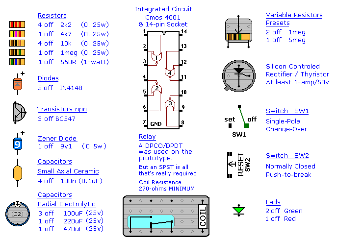
Parts List
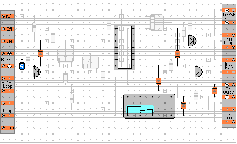
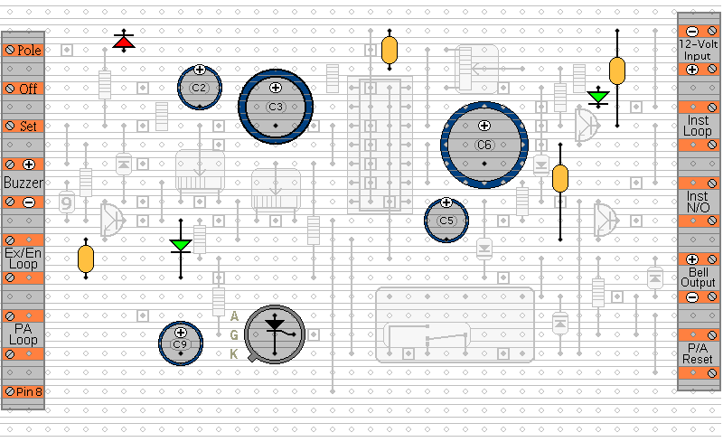
Veroboard Layout
Click here if you're new to constructing stripboard projects.
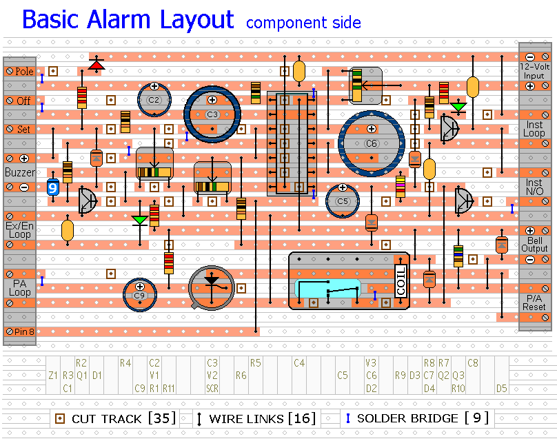
Please note that 2 of the wire links need to be fitted before the IC socket. Also, I used a DPDT or DPCO relay because I thought it might be useful to have a spare set of contacts - but you really only need a SPST.
In the place of Sw1 you may
Connect either the Four-Digit or the Five-Digit alarm keypad.
Construction Guide
The prototype of the Modular Burglar Alarm was built using only the Stripboard Layout as a guide. So - if you reproduce that layout - you will have a working circuit. Details of how to
Test Your Finished Circuit Board are also provided.
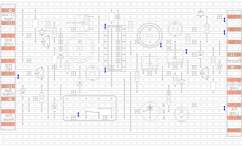
The terminals are a good set of reference points. To fit them - you may need to enlarge the holes slightly. Then turn the board over and use a felt-tip pen to mark the 35 places where the tracks are to be cut. Before you cut the tracks - use the "actual size" drawing to
Check That The Pattern is Correctly Marked .
When you're satisfied that the pattern is right - cut the tracks. Make sure that the copper is cut all the way through. Sometimes a small strand of copper remains at the side of the cut and this will cause malfunction. Use a magnifying glass. It only takes the smallest strand of copper to cause a problem. If you don't have the proper track-cutting tool - then a 6 to 8mm drill-bit will do. Just use the drill-bit as a hand tool - there's no need for a drilling machine.
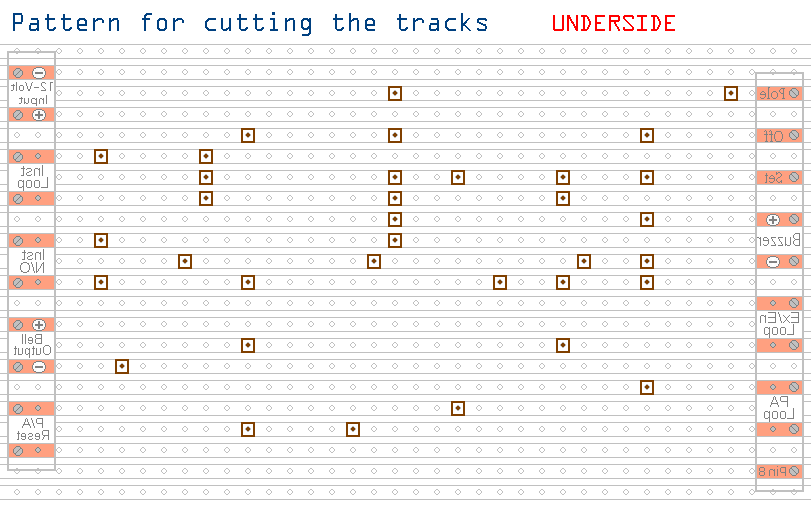
Actual Size Of Pattern
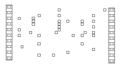
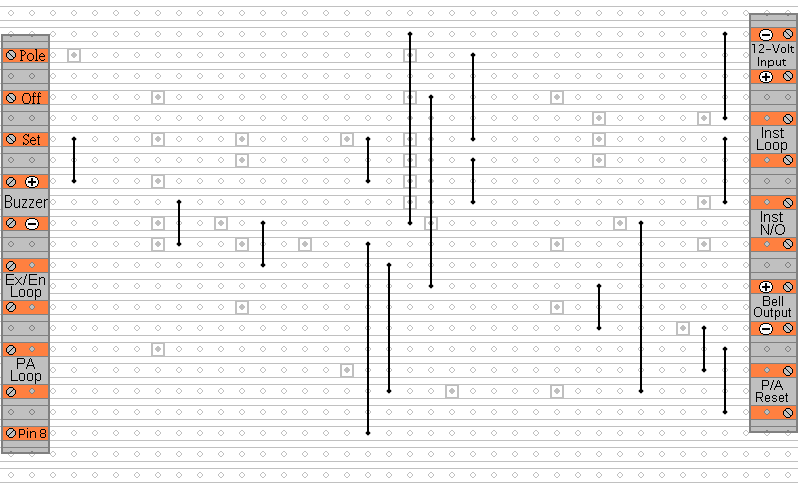
Fit The 16 Wire Links
Next make and fit the
Sixteen Wire Links. I used bare copper wire on the component side of the board. Telephone cable is suitable - the single stranded variety used indoors to wire telephone sockets. Stretching the core slightly will straighten it - and also allow the insulation to slip off.
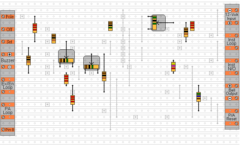
Fit The 11 Resistors And 3 Presets
Next fit the 11 resistors and 3 presets. They're all shown lying flat on the board. But those connected between close or adjacent tracks are mounted standing upright. Set the presets at about mid-point. You can make finer adjustments later to suit your actual requirements.
Fit The Semiconductors - The IC Socket - And The Relay
Now fit the transistors, diodes, IC socket and relay. Again - the diodes are all shown lying flat on the board - but those connected between close or adjacent tracks are mounted standing upright. Pay attention to the orientation of the diodes - particularly the Zener. If it's connected the wrong way round - the Exit/Entry zone will not trigger properly.
Fit The Remaining Components
The Capacitors, the LEDs and the SCR.
You'll want to mount the LEDs where they can be seen - perhaps on the front of your alarm-panel. They should be connected to the circuit board using a light flexible wire - e.g. the cores from a piece of alarm cable. They may be attached to the circuit board from the front or the rear. Make them long to begin with. You can shorten them later when you assemble your alarm-panel. Twist the wires into pairs to keep them tidy.
Add The 9 Solder Bridges
Turn the board over and add the 9 solder bridges to the underside - then examine it carefully - to make sure that there are no unwanted solder bridges or other connections between the tracks.
Finally, insert the 4001 into the socket. Make sure that pin 1 is in the top left-hand corner - and check carefully that all of the pins are correctly inserted into the socket. Sometimes - instead of entering the socket - a pin will curl up underneath the IC.
 SUGGESTIONS