This module allows you to add extra zones to the
Modular Burglar Alarm circuit. Both zones work in the same way. However - their trigger circuits are different. Zone 1 is normally-closed only - and Zone 2 is both normally-open and normally-closed. This configuration was chosen to illustrate the two possibilities. You can decide which type of trigger circuit you want to use - make both zones the same if you wish.
The following circuit description concentrates on the workings of Zone 2. Once its operation is understood - the workings of Zone 1 should be obvious. The Zone 2 trigger is connected to pin 12. This pin is held low by the normally-closed loop and by QZ1 - which is kept switched on by current through RZ11. Current flowing through the transistor and the loop - lights the green LED. This shows that the trigger circuit is closed.
When the alarm is "off" - RZ2 holds pin 13 low. This means that the output of gate 4 has to remain low. See the truth table for the 4081. As long as at least one of its inputs is low then the output will be low also.
When the alarm is "set" - SW1 on the main circuit board takes 'B' high. This takes pin 13 high - and enables gate 4. Now - if the N/C loop is opened - or QZ1 is turned off by a N/O switch connecting its base to ground - RZ10 will take pin 12 high. With both its inputs high - the output at pin 11 will go high. This output does two jobs.
Firstly - by taking pin 8 of the Cmos 4001 high through DZ5 - it triggers the "Instant" zone on the main circuit board.
Secondly - it takes the inputs of gate 3 high through DZ6 and RZ9 - causing pin 10 to go high. Pin 10 also does two jobs.
Firstly - it latches itself on by taking its own inputs high through RZ7 - and secondly - it lights the red LED - to indicate that zone 2 has been activated.
When pin 11 goes low again - either because the alarm has been switched off - or because the trigger circuit has been restored - DZ6 prevents pin 11 from taking pins 8 and 9 low. So the red LED will stay lit - and the module will ''remember'' that zone 2 has been activated.
With the exception of the trigger circuit - zone 1 operates in exactly the same way. The red LEDs indicate where in the building the intruder has tried to gain access - or in the case of repeated false alarms - which zone is giving trouble.
Once you have noted which zone has caused the activation - you may turn-off the red LED by pressing the reset button. This takes pins 8 and 9 low - so the output at pin 10 goes low also. DZ4 allows all the modules to share a single reset button - without their interfering with each other.
Note that the button only turns off the LED. It does NOT reset the zone. The zone resets itself automatically when the trigger circuit is restored - and this happens regardless of whether or not the LED is lighting.
The Two-Zone Module is connected permanently to the 12-volt supply and its operation is enabled when SW1 takes 'B' high. DZ5 allows any number of zones to be connected to 'A' without their interfering with each other. RZ4 limits the current surge as the outputs of gates 1 and 4 charge C5 on the main circuit board.
The 100n capacitors are there to slow down the response time of the gates and to de-tune the alarm loops - so that the alarm will not be activated by radio interference or spikes on the mains supply.
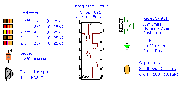
Two Zone Parts
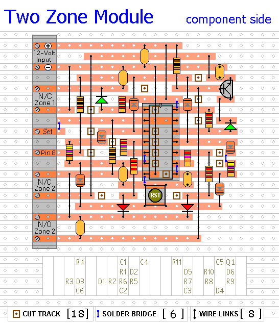
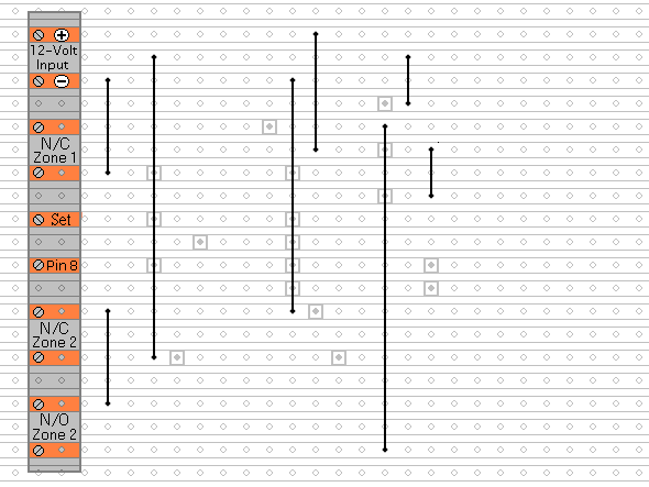
Two Zone Layout
Two Zone Construction Guide
Click here if you're new to constructing stripboard projects.
The prototype of the Two Zone Module was built using only the Stripboard Layout as a guide. So - if you reproduce that layout - you will have a working circuit. Details of how to
Test Your Finished Circuit Board are also provided.
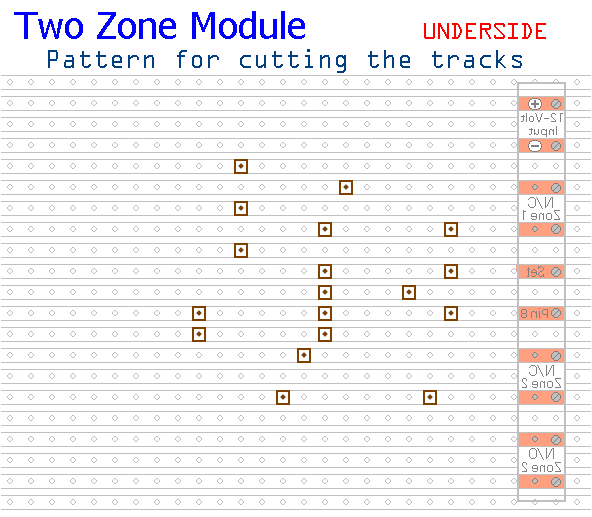
The terminals are a good set of reference points. To fit them - you may need to enlarge the holes slightly. Then turn the board over and use a felt-tip pen to mark the 18 places where the tracks are to be cut. Before you cut the tracks - use the "actual size" drawing to
Check That The Pattern is Correctly Marked .
When you're satisfied that the pattern is right - cut the tracks. Make sure that the copper is cut all the way through. Sometimes a small strand of copper remains at the side of the cut and this will cause malfunction. Use a magnifying glass. It only takes the smallest strand of copper to cause a problem. If you don't have the proper track-cutting tool - then a 6 to 8mm drill-bit will do. Just use the drill-bit as a hand tool - there's no need for a drilling machine.
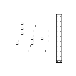
Actual Size Of Pattern
Fit The 8 Wire Links
Next make and fit the
Eight Wire Links. I used bare copper wire on the component side of the board. Telephone cable is suitable - the single stranded variety used indoors to wire telephone sockets. Stretching the core slightly will straighten it - and also allow the insulation to slip off.
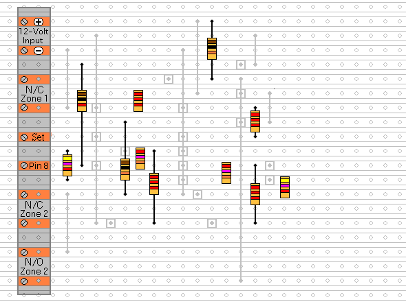
Fit The 11 Resistors
Next fit the 11 resistors. They're all shown lying flat on the board. But those connected between close or adjacent tracks are mounted standing upright.
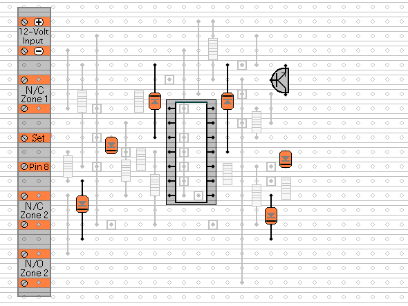
Fit The Diodes, The Transistor And The IC Socket
Again, the diodes are all shown lying flat on the board - but those connected between close or adjacent tracks are mounted standing upright.
Fit The Remaining Components
The Capacitors, The LEDs and The Reset Button.
You'll want to mount the LEDs where they can be seen - perhaps on the front of your alarm-panel. They should be connected to the circuit board using a light flexible wire - e.g. the cores from a piece of alarm cable. They may be attached to the circuit board from the front or the rear. Make them long to begin with. You can shorten them later when you assemble your alarm-panel. Twist the wires into pairs to keep them tidy. Use a similar approach when installing the Reset Button. Any number of expansion modules may be connected to a single Reset Button.
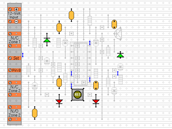
After adding the 6 solder bridges to the underside of the board - examine it carefully - to make sure that there are no unwanted solder bridges or other connections between the tracks. Finally, insert the 4081 into the socket. Make sure that pin 1 is in the top left-hand corner - and check carefully that all of the pins are correctly inserted into the socket. Sometimes - instead of entering the socket - a pin will curl up underneath the IC. You're ready now to
Test Your Finished Circuit Board.
 SUGGESTIONS
