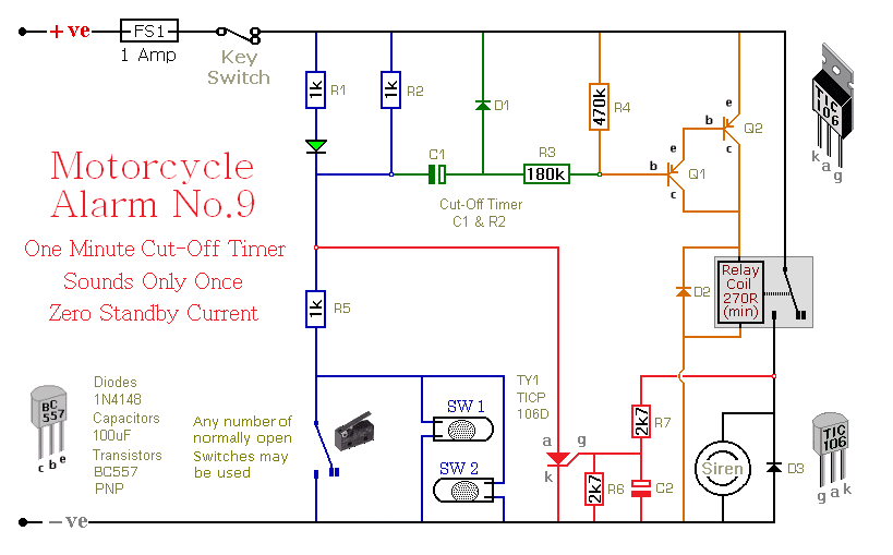
This is a simple "one-time-only" motorcycle alarm. If the bike is moved - the siren will sound for about a minute. Then it will switch off - and remain off. The alarm won't activate a second time. It can't be activated again - until the next time the alarm is set.
Schematic Diagram
Click Here For A Photograph Of The Prototype.

Notes
Any number of normally-open switches may be used. Fit "tilt" switches that close when the steering is moved or when the bike is lifted off its side-stand or pushed forward off its centre-stand. Use micro-switches to protect removable panels and the lids of panniers etc.
The siren will sound for about a minute - until C1 charges through R3 & R4. If you want a bit longer than a minute - you can safely double the value of R3. But - if you want substantially longer than about two minutes - it's best to increase the value of C1 as well.
After the siren switches off - the LED remains lit. If you return to your bike - and find the LED lighting - you'll know that there's been an activation. If you wish - you can replace both R1 and the standard LED - with a single 12v flashing LED. Just connect it from the positive line - to the junction of R2 & R5.
The circuit is designed to use an electronic siren drawing less than about 500mA. It's not usually a good idea to use the bike's own horn - because it can be easily located and disconnected. However - if you choose to use the horn - remember that the alarm relay is too small to carry the necessary current. Connect the coil of a suitably rated relay to the "Siren" output - and use its contacts to sound the horn.
The alarm's standby current is virtually zero - so it won't drain your battery. The circuit board and switches must be protected from the elements. Dampness or condensation will cause malfunction. Connect a 1-amp in-line fuse AS CLOSE AS POSSIBLE to your power source. This is VERY IMPORTANT. The fuse is there to protect the wiring - not the alarm. Exactly how the system is fitted will depend on the make of your particular machine - so I'm unable to provide any further help or advice in this regard.
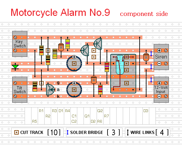
The components are all drawn lying flat on the board - but those connected between close or adjacent tracks are mounted standing upright. The links are bare copper wire on the component side. The
Support Material includes a detailed circuit description, a circuit simulation, a parts list, a step-by-step guide to construction and details of
How To Test Your Finished Alarm .
Veroboard Layout
Click Here For A Photograph Of The Prototype.

Motorcycle Alarm No.9 - Circuit Simulation