The circuit uses a small single pole relay - such as the 12v Omron G2E. The coils of these low voltage DC relays behave just like resistors. I've used a 270 ohm resistor (Ry) to simulate my relay coil. The Differential Voltage Probe measures the voltage across the relay coil. And the state of the relay is determined by the level of that voltage.
You'll see from the graph below that - on activation - the voltage across the coil rises sharply to 12v. This causes the relay to energize - and the siren to sound. About 50 seconds later - the voltage across the coil starts to fall again. When it falls to about four volts - the relay de-energizes - and the noise stops.
Graphs
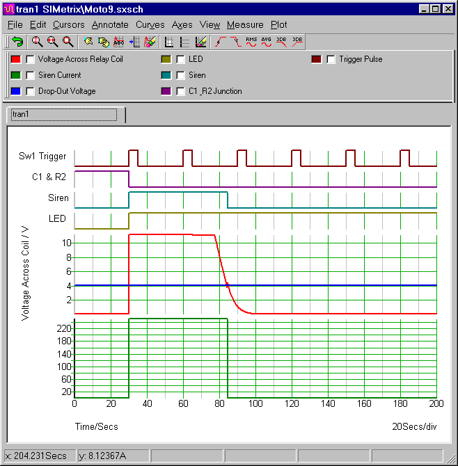
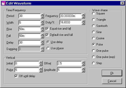
The top line represents the trigger pulses. It's produced by V2. Thirty seconds into the simulation - V2 begins to supply a series of five second pulses. These switch Sw1 on and off. The first time Sw1 closes - it connects the junction of C1 & R2 to ground through R5 - and the alarm activates.
The Trigger Pulse Settings (V2)
It doesn't matter how many more times Sw1 closes. The first time - is the only time that counts. Subsequent V2 pulses will continue to close Sw1 at thirty second intervals. But this has no effect. Sw1 has become redundant. It has been bypassed by Ty1. And the thyristor is now connecting the junction of C1 & R2 - straight to ground. In other words - the alarm can only be activated once.
Analysis Settings
The analysis settings are fairly simple. The "Mode" should be set to "Transient". And the "Stop Time" should be long enough to allow the alarm to complete its activation and siren cut-off sequence. I chose 200 seconds.
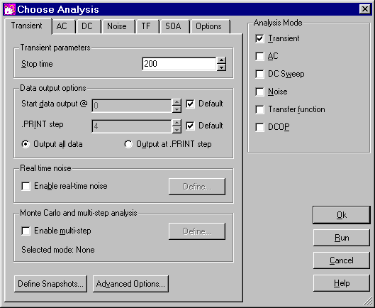
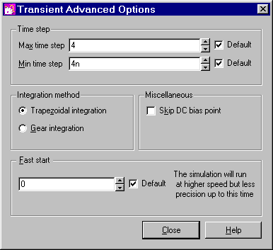
SIMetrix uses your choice of "Stop Time" to calculate some of its "default" settings. If your choice of figure is high - some of the default settings will be too high. And this will prevent the simulation from running successfully.
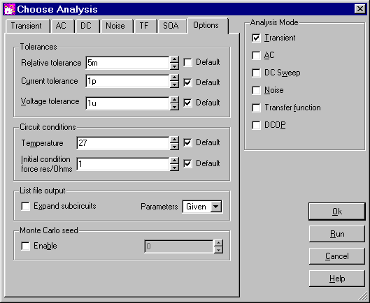
You could solve the problem by changing some of the individual default settings - such as the minimum time step - or the integration method. But for present purposes - I found that it was sufficient to increase the value of the "relative tolerance". All the other settings can remain at their default levels. You'll find the relative tolerance - under the "options" tab.
The Thyristor (Ty1)
The model library that comes with SIMetrix 5.40 doesn't include an SCR. It has to be created as a separate sub-circuit. I created my SCR sub-circuit - using a
Complementary Latch. I'm not suggesting that it's a very satisfactory general purpose SCR model. But it's perfectly adequate for present purposes. If you want to examine the SCR sub-circuit more closely - you'll find it in the download file.
To run the simulation successfully - you'll need to install my SCR model. This is very easy to do. Open SIMetrix - and simply drag and drop the "MyScr.lb" file into the small "SIMetrix Command Shell" window. Then when you're asked - confirm that you want to install the new model. Don't Worry! You're not overwriting anything. All the existing models are still there.