The components used in the circuit should be widely available. However, none of them are critical. So - if you can't find the specified parts -
You're certain to find something that will do just as well.
The alarm is intended primarily for use on a motorcycle. I didn't want the circuit to drain the motorcycle battery - so I designed it to have a zero standby current. This was achieved by using normally-open trigger switches and by making sure that - when the alarm is set - there are no purely resistive connections between the positive rail and ground.
The zero standby current means that the alarm may be powered by dry-batteries. This would make it more secure - because it could not be defeated by disconnecting the motorcycle battery. It also means that the alarm may be used in situations where a power source is not available. For example, it could be fitted inside anything that's in danger of being picked up - and carried away.
"Mercury Tilt Switches" are generally small glass bulbs with two contacts at one end. Inside the bulb is a "ball" of mercury. When the switch is "tilted" a few degrees off the horizontal - the mercury flows to one end and connects the contacts together.
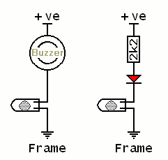
Mercury tilt switches are expensive. You may prefer to use the cheaper "non-mercury" type. The main difficulty with these is that - unlike mercury switches - you can't actually see what's happening inside. This can make them troublesome to position accurately. When setting-up the switching point, you may find it helpful to use a small buzzer - or an LED connected in series with a 2k2 resistor.
Parts List
Click Here For A Photograph Of The Prototype.
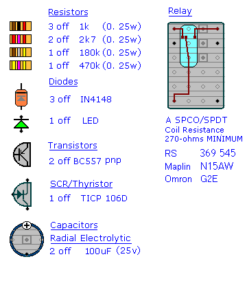
Construction Notes
Click here if you're new to constructing stripboard projects.
The terminals are a good set of reference points. To fit them - you may need to enlarge the holes slightly. Then turn the board over and use a felt-tip pen to mark the 10 places where the tracks are to be cut. Before you cut the tracks - use the "actual size" drawing - to
Check Your Pattern is correctly marked.
Actual Size
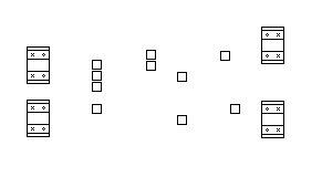
When you're satisfied that the pattern is right - cut the tracks. Make sure that the copper is cut all the way through. Sometimes a small strand of copper remains at the side of the cut and this will cause malfunction. Use a magnifying glass - and backlight the board. It only takes the smallest strand of copper to cause a problem. If you don't have the proper track-cutting tool - a 6 to 8mm drill-bit will do. Just use the drill-bit as a hand tool - there's no need for a drilling machine.
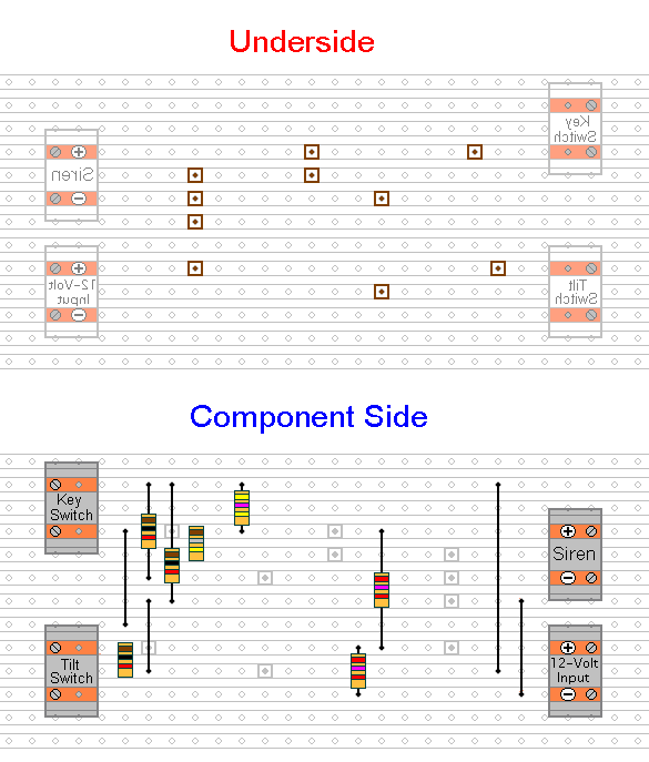
Next fit the 7 resistors and the
Four Wire Links. For the links - I used bare copper wire on the component side of the board. Telephone cable is suitable - the single stranded variety used indoors to wire telephone sockets. Stretching the core slightly will straighten it - and allow the insulation to slip off.
The next stage is to fit the SCR, the 2 transistors and the 3 diodes. The SCR pin connections are marked on the drawing. If you're NOT USING A TICP106D - check the PIN CONFIGURATION of your device. The same goes for the two transistors. Make sure that they're both PNP - and that you know which pin is which. Also - pay particular attention to the orientation of the diodes. All three have their cathodes - the end with the bar - pointing upwards. You'll want to mount the LED remotely - where it can be seen. But for the present - just tack it to the veroboard temporarily.
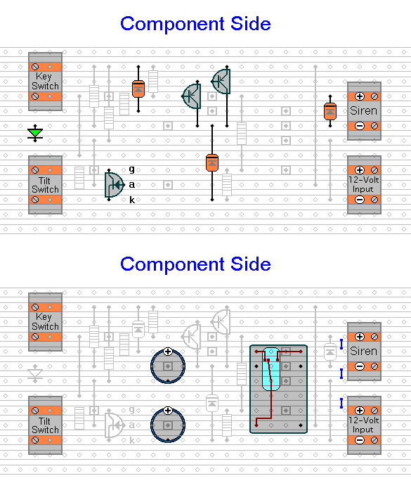
Next - fit the two capacitors and the relay. Radial electrolytic capacitors generally have a stripe down one side of the can - next to the
negative lead. Note that both capacitors are mounted with the
positive terminal towards the top of the board.
Finally - examine the underside of the board carefully - to make sure that there are no unwanted solder bridges or other connections between the tracks. If you backlight the board during the examination - it makes potential problem areas easier to spot.
When you're satisfied that everything is in order - add the 3 solder bridges to the underside of the board. These are just small blobs of solder that connect the adjacent tracks.
You Are Now Ready To Test Your Alarm