All the information you need to build a practical and fully featured burglar alarm system.
Learn More About The Complementary Latch
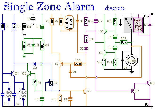
Power Supply
The circuit itself should not use more than a few milliamps. It is only when the relay is energised and the siren is sounding that any real current is required. The actual current consumption depends on the sounder you use. A conventional bell uses up to about 400ma. An electronic siren generally uses less. In any case, a 1-amp power supply should be sufficient. The
Alarm Power Supply is ideal.
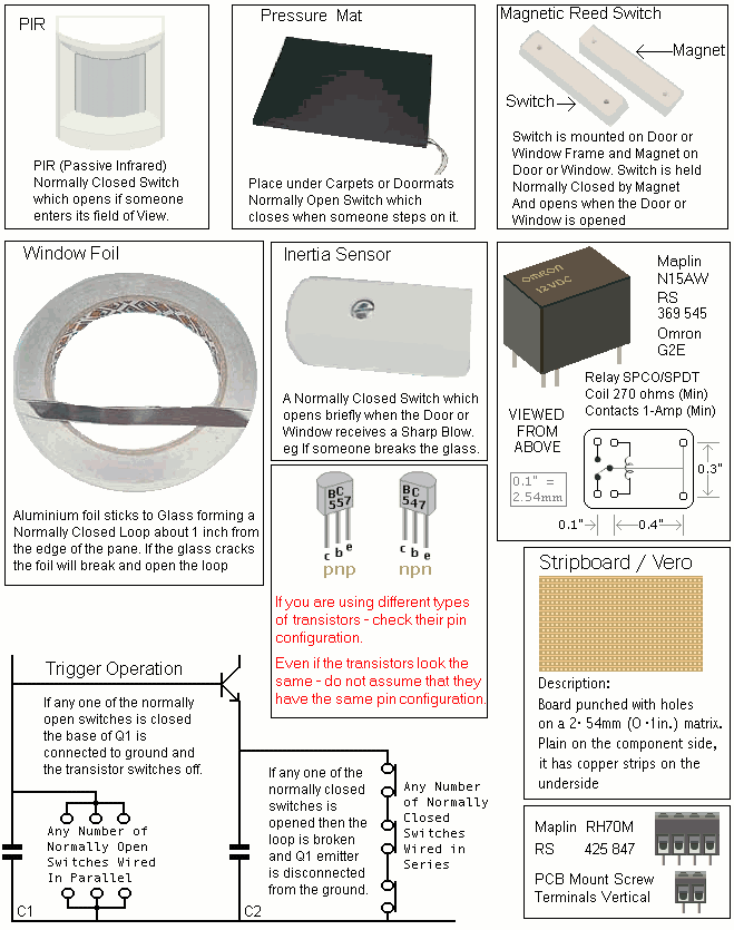
Inertia Sensors
Inertia Sensors are devices that react to vibrations. They do not react to constant low-level vibrations of the sort you would get from loud music or heavy road traffic. Instead they have a certain amount of inertia that must be overcome before they react. In other words they need a sharp blow such as would be required to break a pane of glass.
Essentially - they are small normally-closed switches - the contacts of which are joined by a specially weighted bar. It's the weight of the bar that provides the inertia. When a blow is struck - the bar bounces - and the circuit opens briefly. The length of time the switch is open depends on the strength of the blow - i.e. how high the bar bounces.
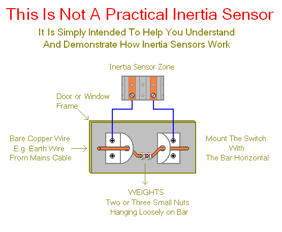
The alarm circuit sensitivity is adjusted by altering the speed at which it reacts:- i.e. the speed at which C6 charges through R8. At its most sensitive - the value of R8 is zero and C6 will charge very quickly. The alarm will react to a very short opening of the circuit. So a light tap on the sensor will do. With R8 set to maximum value - a heavy blow is required.
The Control Switch
Any 1-amp SPST switch may be used to control the alarm. However - you may also use either the 4-Digit Keypad
or the 5-Digit Keypad. The guide to the Alarm's External Connections includes details of how to attach the keypads.
Parts List
|
|---|
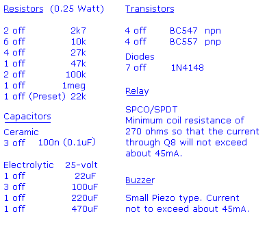
|
|
Construction
Click here if you're new to constructing stripboard projects.
The terminals are a good set of reference points. To fit them - you may need to enlarge the holes slightly. Then turn the board over and use a felt-tip pen to mark the 21 places where the tracks are to be cut. Before you cut the tracks, use the "actual size" drawing to Check That The Pattern is Correctly Marked .
When you're satisfied that the pattern is right - cut the tracks. Make sure that the copper is cut all the way through. Sometimes a small strand of copper remains at the side of the cut and this will cause malfunction. Use a magnifying glass - and backlight the board. It only takes the smallest strand of copper to cause a problem. If you don't have the proper track-cutting tool - then a 6 to 8mm drill-bit will do. Just use the drill-bit as a hand tool - there's no need for a drilling machine.
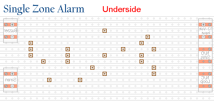
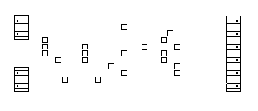
Actual Size Of Pattern
Next make and fit the Six Wire Links. I used bare copper wire on the component side of the board. Telephone cable is suitable - the single stranded variety used indoors to wire telephone sockets. Stretching the core slightly will straighten it - and also allow the insulation to slip off.
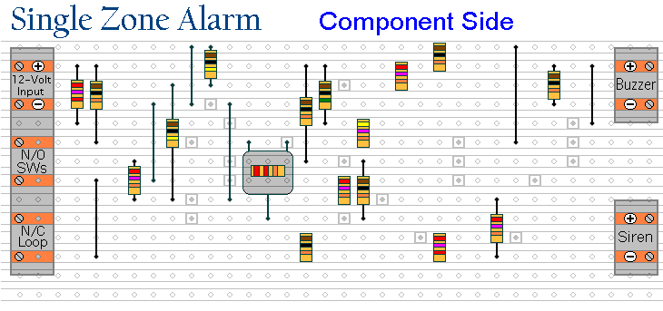
Then fit the 17 resistors. They're all shown lying flat on the board. But those connected between close or adjacent tracks are actually mounted standing upright. See the Photograph Of The Prototype
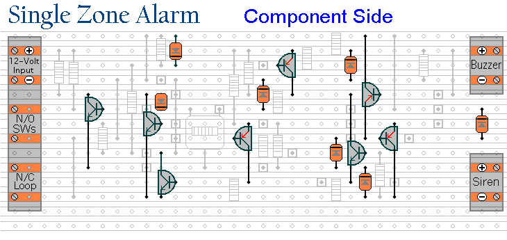
Now fit the transistors and diodes. The BC557 (pnp) transistors are those with the emitter arrow coloured red. Pay particular attention to the orientation of the diodes. Note that D1 and D2 face in a different direction from the rest - and that D2 is mounted standing upright.
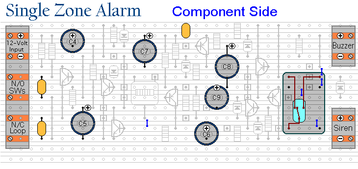
Finally - fit the nine capacitors and the relay. Pay particular attention to the orientation of the electrolytic capacitors. They generally have a light coloured stripe down the side next to the negative terminal. Note that all the electrolytic capacitors have their negative terminals facing the bottom of the board. See The Photo Of The Prototype
Examine the underside of the board carefully - to make sure that there are no unwanted solder bridges or other connections between the tracks. If you backlight the board during the examination - it makes potential problem areas easier to spot. When you're satisfied that everything is in order - add the 5 solder bridges.
You Are Now Ready To Test Your Finished Circuit Board
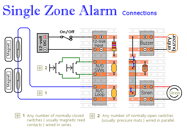
Connections
Modification

General Information
Click Here For A Photograph Of The Prototype
 SUGGESTIONS