This simple toggle switch circuit will energize and de-energize alternate relays with a simple non-latching push-button.
Click Here For A Detailed Circuit Description
This versatile circuit provides a selection of different switching modes. It can be used as two entirely separate toggle switches. Or the two toggle switches can be inter-connected with diodes. Then operating one of the switches - will influence the behaviour of the other - and vice versa. The flow chart below describes how the circuit will behave when D2, D3, D4 & D5 are all present.
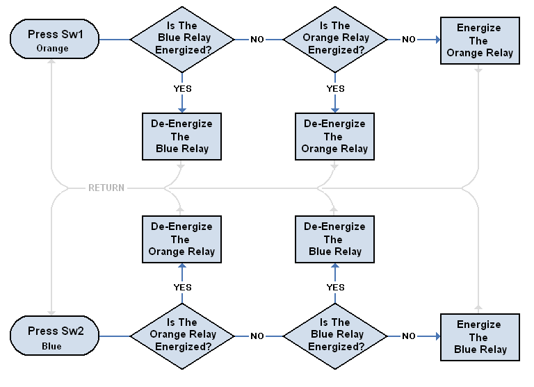
The circuit powers up with both relays de-energized. And the following describes what happens when you push Sw1 - the orange button. Pushing Sw2 - the blue button - produces similar results.
While the blue relay is de-energized - successive pushes of the orange button will energize and de-energize the orange relay. But - if the blue relay is energized - the first push on the orange button will de-energize the blue relay - and a second push is required to energize the orange relay.
In other words - you can't switch directly from one relay to the other. There is always an intermediate stage - during which both of the relays are de-energized. If you do want to switch directly from one relay to the other - leave out D2 & D5
 SUGGESTIONS
