This simple toggle switch circuit will reverse the direction of a DC motor.
Click Here For A Detailed Circuit Description
Two Interlocking Toggle Switches
This versatile circuit provides a selection of different switching modes. It can be used as two entirely separate toggle switches - with each push button successively energizing and de-energizing its own relay. Or the two switches can be interlinked with diodes - to produce a number of different switching patterns. For example - the circuit can be used to reverse the direction of DC motors.
Click Here For A Photograph Of The Prototype
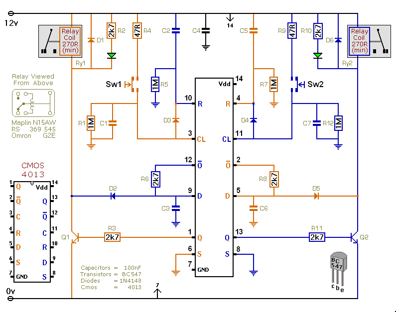
D3 allows the orange push button to de-energize the blue relay. And D4 allows the blue push button to de-energize the orange relay. In other words - if the blue relay is energized - it will drop out when you press the orange button. And - if the orange relay is energized - it will drop out when you press the blue button.
While the blue relay is energized - D5 & Q2 hold the orange data pin low. This prevents the orange push button from energizing the orange relay. Similarly - while the orange relay is energized - D2 & Q1 hold the blue data pin low. So the blue push button can't energize the blue relay. In other words - the two relays can't be energized at the same time. You have to de-energize the first - before you can energize the second. And vice versa.
I've drawn the circuit with all four diodes present. And the accompanying Flow Chart describes how each switch will behave. Basically - each button will toggle its own relay. But you can't switch directly from one relay to the other. There's a "centre-off" position - when both relays are de-energized.
The circuit will work at anything from 5 to 15-volts. All you need do is choose relays with a coil voltage that suits your supply. I've drawn single pole relays. But you can use multi-pole relays - if they suit your application.
 Do not use the "on-board" relays to switch mains voltage. The board's layout does not offer sufficient isolation between the relay contacts and the low-voltage components. If you want to switch mains voltage - mount suitably rated relays somewhere safe - Away From The Board.
Veroboard Layout
Click Here For A Photograph Of The Prototype
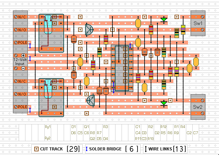
The Support Material for this circuit includes a parts list - a step-by-step guide to the construction of the circuit-board - a detailed circuit description - simple modifications that will change the switching pattern - and more.
Interlocked Toggle Switches - Support Material
 SUGGESTIONS
