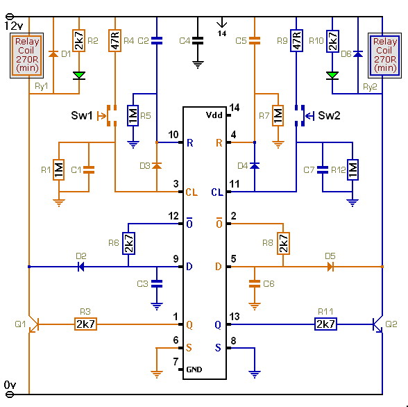
This simple toggle switch circuit will energize and de-energize a relay - at the push of a button.
Changing The Behaviour
If you leave out D2, D3, D4 & D5 you'll have two independent toggle switches. Successive pushes on the orange button will energize and de-energize only the orange relay. And the blue button will behave in a similar manner.
If you keep D3 and D4 then - as well as energizing its own relay - each button will de-energize the opposing relay. This means that you can switch back and forth from one relay to the other. It also means that the two relays can never be energized at the same time. As soon as you energize one - the other drops out.
If you keep D2 and D5 - the blue switch can disable the orange button - and the orange switch can disable the blue button. This means that you have to de-energize the blue relay - before you can energize the orange relay - and vice versa. In other words - you can't switch directly from one relay to the other. There has to be an intermediate stage - during which both relays are de-energized.
You can also mix and match these effects. If you leave out D2 & D3 - you can create a Master/Slave relationship. The blue switch can disable the orange push button - but the orange switch cannot disable the blue push button. In other words - Sw2 can both de-energize the orange relay and energize the blue relay - at any time. But Sw1 can only energize the orange relay - if the blue relay is already de-energized.
Of course - if you can use diodes to interconnect two toggle switches - you can use diodes to interconnect any number of toggle switches. So - once you have a clear understanding of the behaviour you require - all you need do is design a suitable diode network.
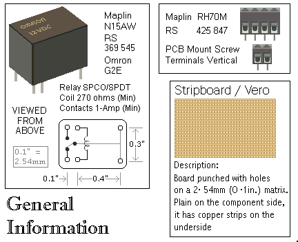
Parts List
|
|---|
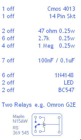
|
|
|
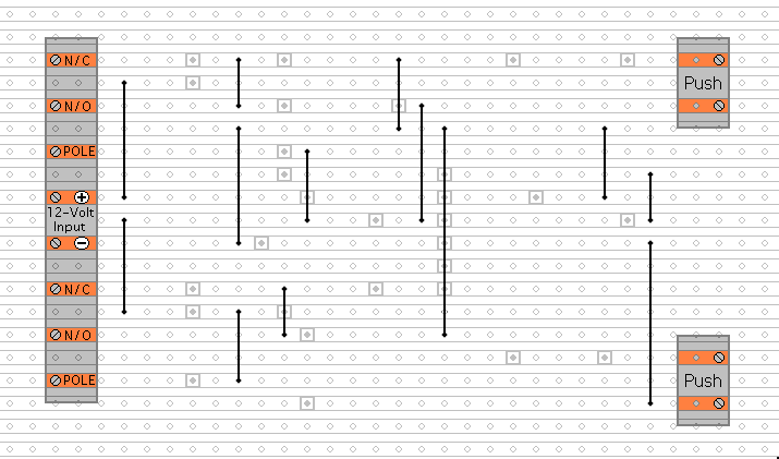
Construction Guide
Click here if you're new to constructing stripboard projects.
The prototype of this circuit was built using only the Stripboard Layout as a guide. So - if you reproduce the layout - you will have a working circuit. Details of how to Test Your Finished Circuit Board are also provided.
The terminals are a good set of reference points. To fit them - you may need to enlarge the holes slightly. Then turn the board over and use a felt-tip pen to mark the 29 places where the tracks are to be cut. Before you cut the tracks - use the "actual size" drawing to Check That The Pattern is Correctly Marked .
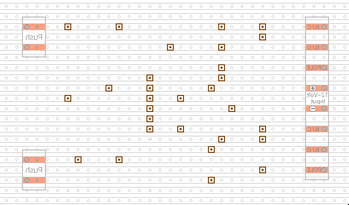
Actual Size
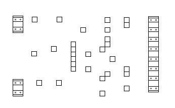
When you're satisfied that the pattern is right - cut the tracks. If you don't have the proper track-cutting tool - then a 6 to 8mm drill-bit will do. Just use the drill-bit as a hand tool - there's no need for a drilling machine. Make sure that the copper strip is cut all the way through. Sometimes a small strand of copper remains at the side of the cut and this will cause malfunction. Use a magnifying glass - and backlight the board. It only takes the smallest strand of copper to cause a problem.
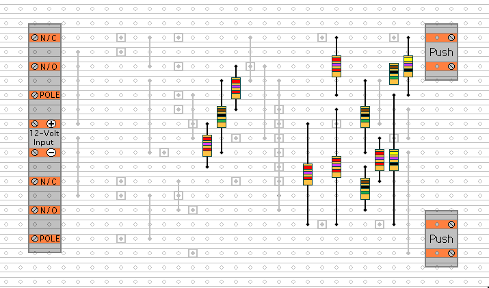
Next fit the Thirteen Wire Links. For the links - I used bare copper wire on the component side of the board. Telephone cable is suitable - the single stranded variety used indoors to wire telephone sockets. Stretching the core slightly will straighten it - and also allow the insulation to slip off.
Then fit the twelve resistors. For clarity - all the resistors are drawn lying flat on the board. However - R1 is actually mounted standing upright. See the Photograph Of The Prototype.
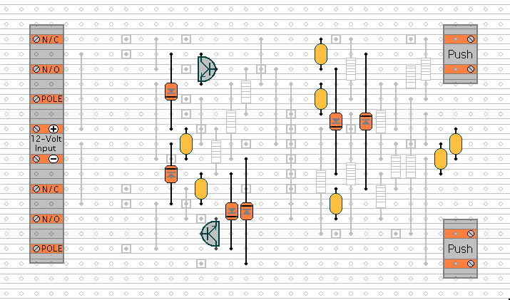
Next - fit the six diodes - the two transistors - and the seven capacitors. Pay particular attention to the orientation of the diodes and transistors. See the Photograph Of The Prototype.
Finally - fit the two relays - the IC socket - and the LEDs. Pay particular attention to the orientation of the LEDs.
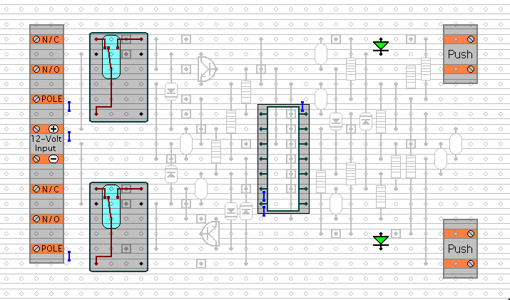
Turn the board over and examine the underside carefully - to make sure that there are no unwanted solder bridges or other connections between the tracks. If you backlight the board during the examination - it makes potential problem areas easier to spot. When you're satisfied that everything is in order - add the 6 solder bridges. The solder bridges are just small blobs of solder connecting the two tracks together. They're like very short wire links.
Finish off by inserting the Cmos IC into the socket. Pin 1 of the IC should be in the top left-hand corner. Check that all 14 pins have entered the socket. Sometimes - instead of entering the socket - a pin will curl up under the IC.
You Are Now Ready To Test Your Finished Circuit Board.
General Information
Click Here For A Photograph Of The Prototype.
 SUGGESTIONS