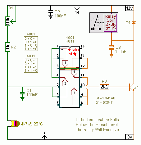
These two circuits allow you to set the temperature at which the relay will energize and de-energize.
The first circuit energizes the relay when the temperature rises above the preset level. The second circuit energizes the relay when the temperature falls below the preset level. The two circuits are practically identical. The only difference between them is the polarity of the transistor. The value of the thermistor is not critical. The important thing is the voltage on pins 5 & 6. Any value thermistor should work satisfactorily. But you may need to change the value of R1 - to achieve the desired range of adjustment.
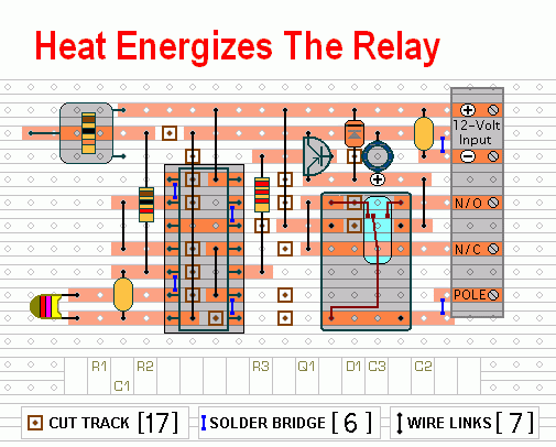
Circuit No.1
 Do not use the "on-board" relay to switch mains voltage. The board's layout does not offer sufficient isolation between the relay contacts and the low-voltage components. If you want to switch mains voltage - mount a suitably rated relay somewhere safe - Away From The Board.
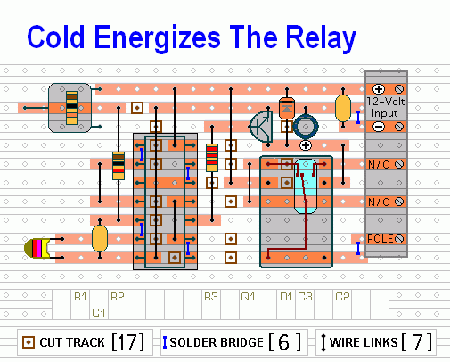
Circuit No.2
Temperature Range
Roughly speaking - the operating temperature will adjust from about 5şC to 75şC (41şF to 167şF). However - this wide range makes the adjustment coarse. You can improve control by reducing the value of the pot and increasing the value of R2. Use R2 to take you close to the desired temperature - and use the reduced value pot to make the fine adjustment.
The relay is actually controlled by the voltage on pins 5 & 6. So - by changing the value of R2 - you can extend the range in either direction. Increasing the value of R2 - will give access to lower temperatures. And - reducing the value of R2 - will give access to higher temperatures.
The following readings will give you some idea of what to expect. They are taken from the prototype. And they were made using a cheap digital multimeter and a cheap thermometer. They are intended for guidance only. You should NOT expect to get identical readings.
My thermistor measured 4.45K at 25şC (77şF). My supply voltage measured 12v4. And the switching point of gate 2 was measured at about 6v7. With R1 set to 3k - the relay energized / de-energized at a temperature of about 24şC (75şF). Reducing the value of R1 (turning it to the right) increases the temperature. Increasing the value of R1 (turning it to the left) reduces the temperature.
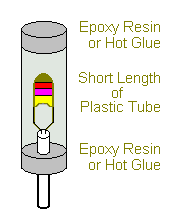
The Temperature Sensor
The mass of the thermistor is small - and it will react quickly to changes in temperature. This makes it sensitive to thermal currents. One solution is to create an enclosed environment - where the thermistor is protected from momentary draughts - but can still respond to slower changes in the overall ambient temperature. Another solution is to increase its mass - by attaching it to a small metal heatsink.
Setting the operating temperature is best carried out "in situ" using trial-and-error. If the relay reacts at too low a temperature - turn R1 a little to the right. If it reacts at too high a temperature - turn R1 a little to the left.
Which Circuit Should I Use?
In order to minimize power consumption - choose the circuit that will have its relay energized for the shorter time period. If it's going to be cold most of the time - choose the circuit that energizes the relay when it gets hot (Circuit No.1). If it's going to be warm most of the time - choose the circuit that energizes the relay when it gets cold (Circuit No.2).
The Supply Voltage
The circuits are designed for a 12-volt power supply. However - they will both work at anything from 5 to 15-volts. All you need do is select a relay with a coil voltage that suits your supply. And make sure that the coil doesn't draw more than about 50mA - otherwise the transistor might be overloaded. I've used a single-pole relay in the diagrams - but you can use a multi-pole relay if it suits your application. The Support Material for this circuit includes a parts list - a step-by-step guide to the construction of the circuit-board - a detailed circuit description - and more.
 SUGGESTIONS