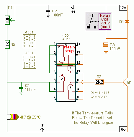
The potentiometer lets you set the temperature at which the relay energizes and de-energizes.
Learn More About Cmos Inverters
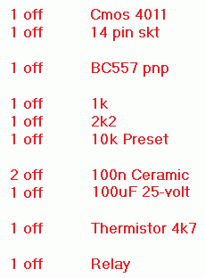
Circuit No.1 - Parts List
|
|
|
|
Circuit No.2 - Description
Click Here For A Photograph Of The Prototype.
|
|
|
|
Learn More About Cmos Inverters
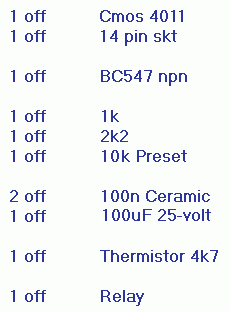
Circuit No.2 - Parts List
|
|
|
|
Construction Guide
Click here if you're new to constructing stripboard projects.
The prototypes of both circuits were built using the same construction guide. The two layouts are virtually identical. The only difference between them is the type and orientation of the transistor.
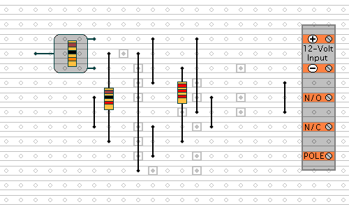
The terminals are a good set of reference points. To fit them - you may need to enlarge the holes slightly. Then turn the board over and use a felt-tip pen to mark the 17 places where the tracks are to be cut. Before you cut the tracks - use the "actual size" drawing to
Check That The Pattern is Correctly Marked .
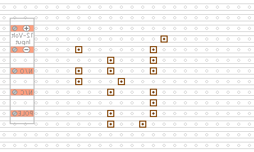
Actual Size
When you're satisfied that the pattern is right - cut the tracks. If you don't have the proper track-cutting tool - then a 6 to 8mm drill-bit will do. Just use the drill-bit as a hand tool - there's no need for a drilling machine. Make sure that the copper strip is cut all the way through. Sometimes a small strand of copper remains at the side of the cut and this will cause malfunction. Use a magnifying glass - and backlight the board. It only takes the smallest strand of copper to cause a problem.
Next - fit the
Seven Wire Links - the preset - and the two fixed resistors. For the links - I used bare copper wire on the component side of the board. Telephone cable is suitable - the single stranded variety used indoors to wire telephone sockets. Stretching the core slightly will straighten it - and also allow the insulation to slip off.
Next - fit the diode and the three capacitors. Pay particular attention to the orientation of both the diode and the electrolytic capacitor. See the
Photograph Of The Prototype. Then - fit the relay - the IC socket - and the thermistor.
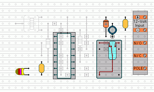
Turn the board over and examine the underside carefully - to make sure that there are no unwanted solder bridges or other connections between the tracks. If you backlight the board during the examination - it makes potential problem areas easier to spot. When you're satisfied that everything is in order - add the 6 solder bridges.
Fit The Transistor
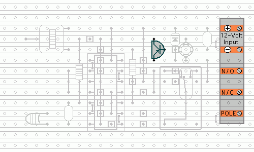
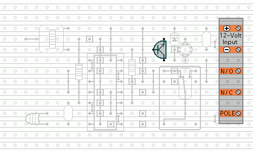
So far - the construction of both Circuits 1 & 2 is identical. All that remains now is to fit the correct transistor. For Circuit No.1 - it's a PNP transistor. For circuit No.2 - it's an NPN transistor. Note that the transistors face in opposite directions. In Circuit No.1 - the BC557 faces left. And in Circuit No.2 - the BC547 faces right.
Circuit No.1 - BC557 PNP
Circuit No.1 - Photo
Circuit No.2 - BC547 NPN
Circuit No.2 - Photo
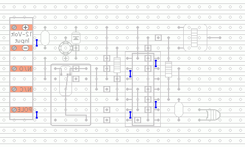
Finish off by inserting the Cmos IC into the socket. Pin 1 of the IC should be in the top left-hand corner. Check that all 14 pins have entered the socket. Sometimes - instead of entering the socket - a pin will curl up under the IC.
You Are Now Ready To Test Your Finished Circuit Board.
 SUGGESTIONS

