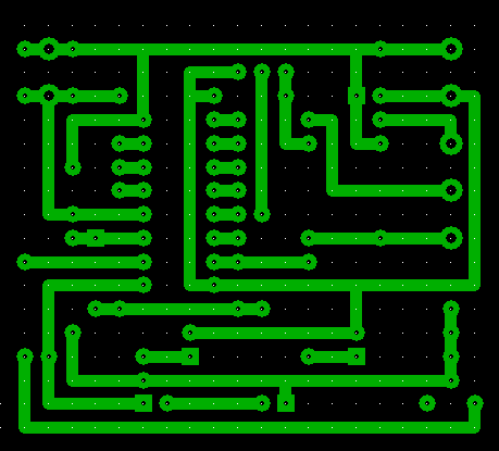
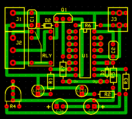
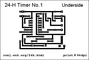
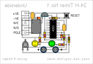
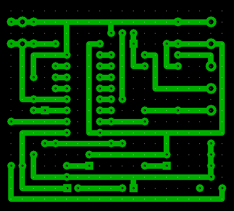
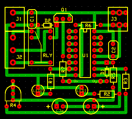
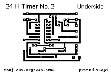
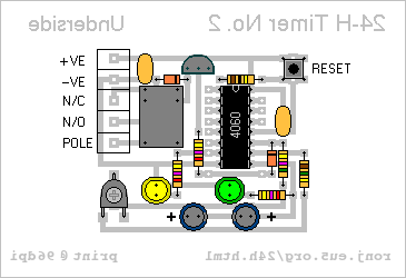
I drew the layouts with a PCB design programme that's available for free from
ExpressPCB. I've made provision for various sizes of preset - including both horizontal and vertical. And the boards will accommodate either two polarized capacitors - or a single non-polarised capacitor. Simply rotate the non-polarised C3 through 90 degrees.
At first sight - the positioning of the components on both boards - appears identical. However - there is one very important difference. Pay particular attention to the orientation of D2. The reset switch may be fitted remotely - via terminals. Or you can mount a small momentary-action push-to-make switch on the PCB itself. The "Range" link connects from either Qx or Qy to the required 4060 output pin.


