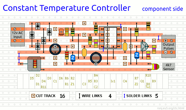
All the information you need to build a simple precise Temperature Controller - using a few cheap off-the-shelf components.

If You Are Not Experienced In Dealing Safely With Mains Power -
|
Constant Temperature Controller
This circuit works like a dimmer switch. While the temperature is rising - the controller is gradually turning the heater's output down. At the preset level - when the heat output exactly matches the heat loss - the temperature will stabilize. And the controller maintains this stability - by making one-hundred fine adjustments to the heater's output - every second.
It can't cope with large or rapid changes in - say - air temperature. It needs an enclosed environment. It's at its best when it's maintaining the temperature of a liquid - such as water. Like a flywheel - the heat energy stored in the liquid mass - will itself tend to resist any significant temperature fluctuations. In a well insulated environment with a small heat-loss - a relatively low-wattage heater will maintain the temperature. For many years - the previous (over complicated) version of this circuit - used a 50-Watt heated mat - to keep my homebrew fermentation vessel (a 5-gallon plastic bucket) at a steady 20°C (68°F). Schematic Diagram

NotesThe heater is controlled by the triac (TIC 206D). The triac is controlled by the optical isolator (MOC 3021). And the optical isolator is driven by the pulses that come from pin 7 of the LM358N. Each pulse turns the heater on briefly. And varying the width of the pulses - varies the heater's output. This circuit is not suitable for inductive loads - such as fans or fan-heater. It's only suitable for heaters with resistive elements. I suggest you build the high-voltage output module into an extension socket. Then you can plug the heater directly into the socket. To test the output module separately - plug a 40-Watt tungsten lamp into the socket - and use a 9v/12v battery to drive the optical-isolator's diode - via R12. I haven't provided a construction guide for the output module. If you're experienced in dealing with mains electricity - you'll already know how to build it safely. If you're not experienced in dealing with mains electricity find someone who is - or leave this project alone. Your life (and that of others) may depend on it. The low-voltage control circuit needs very little current - no more than about 30mA. Use a small 12v transformer (1.5VA or lower). The input must be AC. The 50/60Hz signal from the secondary coil - is used to synchronize the pin 7 output pulses - with the AC mains voltage that powers the heater. R11 sets the temperature. My range of adjustment was roughly 24°C to 48°C (75°F to 118°F). Don't expect to get exactly the same range. Manufacturing tolerances - environmental factors - your choice of heater - the position of the sensor etc. - are bound to have some influence on your results. To access a lower temperature range - increase the value of R10. To access a higher temperature range - reduce the value of R10. I've positioned R10 so that it may be tacked - temporarily - to the right-hand edge of the board. Use trial-and-error - until you get to the range you're after. Veroboard Layout

|


