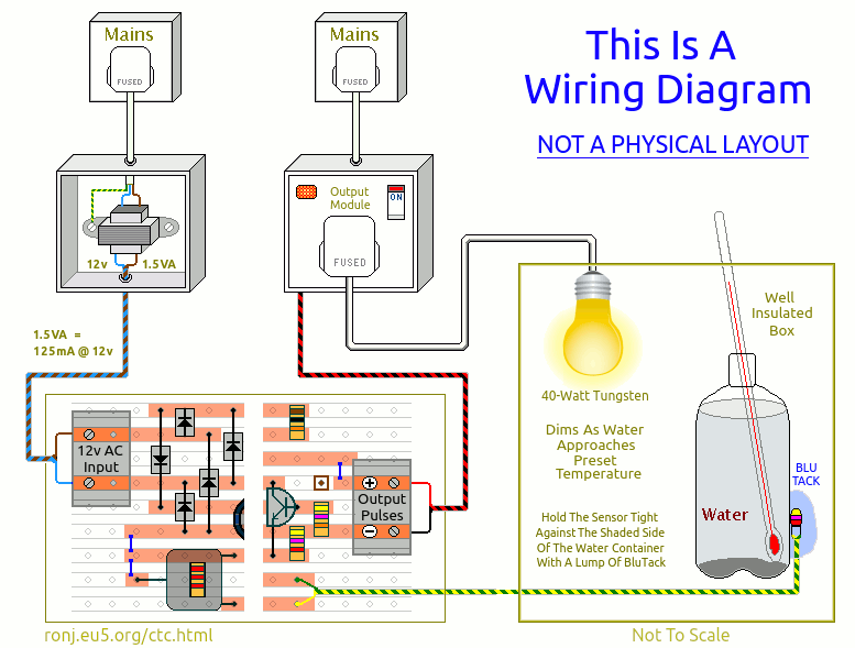
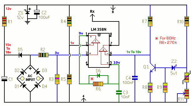
All the information you need to build a simple Precision Temperature Controller - using a few cheap off-the-shelf components.
Introduction
Once you're satisfied that your layout is correct - and you have made a careful and thorough check of the underside of the board - it's time to power-up the circuit and test its operation. Note that the low voltage section of the controller requires 12v AC. If you use a DC Supply - the circuit will not work.
Below - R12, R13, MOC 3021, TIC 206D & Fuse - are all mounted inside the output module. And the heat source - here a 40-Watt tungsten bulb - plugs into the socket. Test the output module - before you add the control board. When you connect a small 9v battery to the red and black wires - the bulb should light. Fit a 3k8 resistor in place of the thermistor. And connect the output module to the control board. The resistor simulates about 30°C (86°F). Rotating R11 clockwise should turn the light on. And rotating it anticlockwise should turn the light off. With a single-turn pot - control is fairly coarse. So your aim is simply to confirm that - at some point in its rotation - R11 actually turns the bulb off. Remove the 3k8 resistor - and replace it with the thermistor. Turn R11 to the left - until the bulb begins to dim. If you've turned R11 all the way to the left - and the bulb still hasn't dimmed - don't worry. It just means that your ambient temperature is below about 20°C (68°F). Place the thermistor about one-centimetre (½ inch) from the bulb. As it warms the thermistor - the bulb should begin to dim - and then probably turn off. Setup
Hang the bulb inside a well insulated box. Then fill a 500ml (1 pt) plastic drinks bottle with water. And use a largish lump of BluTack - to hold the thermistor in close contact with the bottle's surface. The idea is to insulate the thermistor from the surrounding air - while allowing it to respond to changes in the temperature of the water. Placing the sensor behind the bottle - helps shield it from the bulb's radiated heat.
Turn R11 slowly to the right - until the bulb just about reaches full brightness. Then close the box - and wait. It will take a while for the temperature to stabilize. But as it rises - the bulb will slowly dim. If you can't actually see the bulb - plug a second 40-Watt tungsten lamp into the output module - and watch it dim instead.
Be patient. Warm water rises. So to begin with - the heat energy may not be distributed evenly throughout the liquid. Note also that - as the preset temperature approaches - the heater's output is at its lowest. So it will take relatively longer - to add the final degree or so. When the temperature has been stable for several hours - it's time to try a different setting. To raise the temperature - turn R11 to the right (bulb gets brighter). And to lower the temperature - turn R11 to the left (bulb turns off). Note that the ambient temperature - is the lowest temperature you can achieve.
|


