This circuit has two independently adjustable 24-hour timers. The "Relay-Timer" controls the length of time the relay remains energized. And the "Repeat-Timer" controls the rate at which the relay-timer repeats. In other words - the repeat-timer restarts the relay-timer at regular intervals.
Using trial and error to set long delays is very tedious. The tables below provide a better solution. The top table tells you the approximate range of delay available at each output pin. And the lower tables tell you how to convert that delay - into a more convenient time setting.
Ic2 is the relay-timer. Let's say you want the relay to remain energized for one-hour. The top table tells you that a range of 30 to 90 minutes is available at pin 15. And the bottom table tells you that pin 15 takes 64-times longer than pin 7 - to go high.
There are 3 600 seconds in one-hour. If you divide this by 64 - you get a pin 7 setting of roughly 56-seconds. When you connect R15 to pin 15 of Ic2 - and you adjust R14 so that LED3 lights 56-seconds after power is applied to the circuit - the relay will de-energize after one-hour.
Ic1 is the repeat-timer. Suppose you want the relay-timer to restart every six-hours. The top table tells you that a range of 4 to 12 hours is available at pin 2. And the centre table tells you how to calculate the corresponding - and much shorter - pin 5 setting.
There are 21 600 seconds in six-hour. If you divide this by 512 - you get a pin 5 setting of roughly 42-seconds. When you connect C1 to pin 2 of Ic1 - and you adjust R9 so that LED1 lights 42-seconds after power is applied to the circuit - the relay-timer will restart every six-hours.
Notes
If you increase the value of the packing resistors (R8 & R13) - and reduce the values of the pots (R9 & R14) by a corresponding amount - you can set the time delays more precisely. Select values for R8 & R13 that takes you close to the delays you're after. Then use lower value pots to make the fine adjustment. Even finer adjustments are possible if the pots are multi-turn.
If you want the LEDs to glow brighter - use brighter LEDs. Don't be tempted to reduce the values of the series resistors - especially R4 & R11. If you reduce their value too far - the counters may not advance reliably.
The LEDs are there to help you set the delays. They are not necessary to the operation of the timer. And you may want to remove them from your finished device. Note that the green LEDs have a small effect on the speed of the oscillators. So they should be removed before you make your final adjustments. The yellow LEDs have no effect on the speed of the oscillators. They can be removed at any time.
The reset button is optional - but it should NOT be used during setup. The time it takes for the yellow LEDs to light - MUST be measured from the moment power is applied.
Ideally C4 & C6 should be non-polarized 10uF capacitors. Alternatively - you can simulate a non-polarized 10uF capacitor by connecting two polarized 22uF capacitors back to back - as shown in the schematic diagram. Since non-polarized capacitors are more difficult to source - I've used pairs of regular 22uF capacitors in the prototype. If you need longer than 24-hours - increase the value of C4 and/or C6.
The timer is designed for a 12-volt supply. However - provided a suitable relay is used - the circuit will work at anything from 5 to 15-volts. Applying power starts the timer. And it can be reset at any time by a brief interruption of the power supply.

Do not use the "on-board" relay to switch mains voltage. The board's layout does not offer sufficient isolation between the relay contacts and the low-voltage components. If you want to switch mains voltage - mount a suitably rated relay somewhere safe -
Away From The Board.
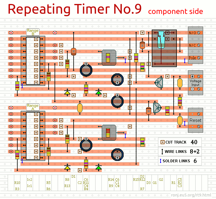
Veroboard Layout
The
Links are bare copper wire - and they are mounted on the component side of the board. The two additional links are used to connect C1 & R15 to your selected range pins. The
Support Material for this circuit includes free simulation software, a detailed circuit description, a step-by-step guide to construction and details of
How To Test Your Finished Timer.
