You can use the free SiMetrix Circuit Simulator to run My Simulation. Or you can use my observations, tips and techniques - to help you create a suitable file for a different simulator programme. If you do decide to create your own simulation - it's still worthwhile downloading SiMetrix - just to compare my results.
SiMetrix Screenshot
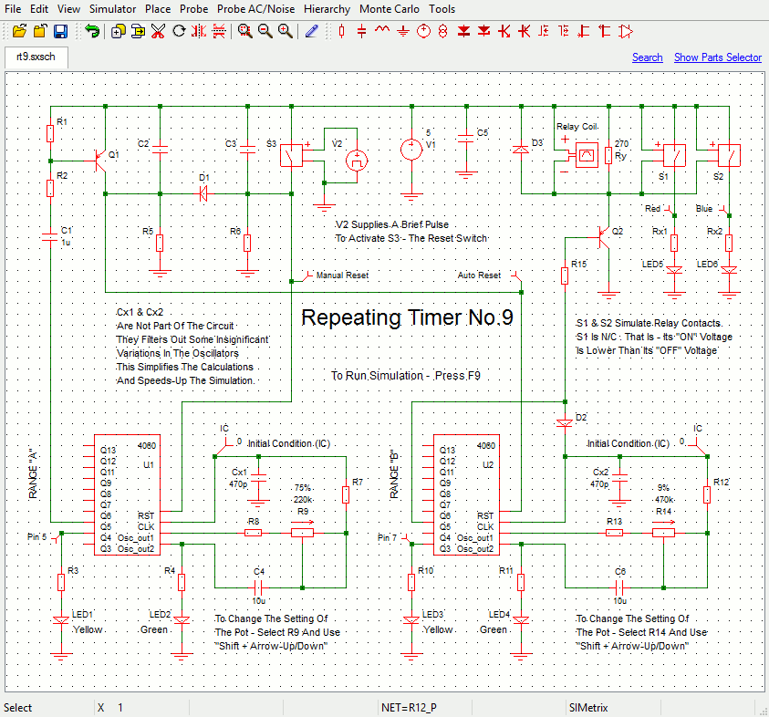
The circuit uses a small single pole relay - such as the 12v Omron G2E. The coils of these low voltage DC relays behave just like resistors. I've used a 270 ohm resistor (Ry) to simulate my relay coil. The Differential Voltage Probe measures the voltage across the relay coil. And the state of the relay is determined by the level of that voltage.
The graph below shows that when power is applied to the circuit - the relay will energize. Two-minutes later - when yellow LED3 switches off for the second time - the relay will de-energize. It will remain de-energized for the next five-minutes. That is - until the yellow LED1 - switches off for the second time.
Ic1 is on a repeating cycle. Every seven-minutes - it restarts the two-minute relay timer. In other words - there is a continuously repeating sequence of two-minutes On - and five-minutes Off.
Graphs
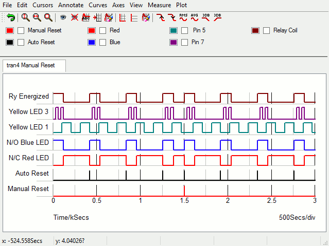
This regular seven-minute cycle - is interrupted at 1500-seconds - when the manual reset button is "pushed". The button resets both ICs. It energizes the relay - and starts a new seven-minute cycle. It's exactly the same as powering the circuit down - and then up again.
The Manual Reset Pulse (V2)
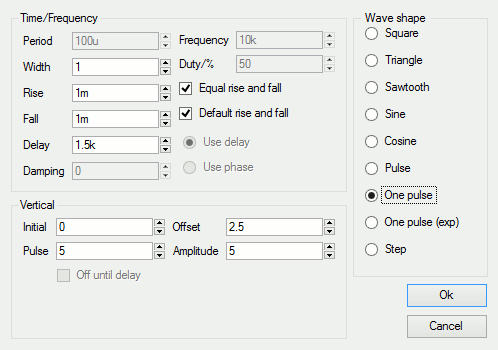
Sw3 represents the reset button. It's controlled by the wave-form generator (V2). After an initial delay of 1500 seconds - V2 delivers a single one-second long output pulse. The pulse closes Sw3. And the switch takes both reset pins briefly high.
Power Supply Setting
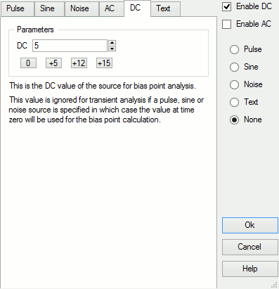
The default power source is 5vdc. If you ever need to change that value - select the power source symbol (e.g. V1 in the schematic) - and press F7. Then change the contents of the "Parameters" window - by typing in your new value. Alternatively - you can simply use one of the preset buttons provided.
Analysis Settings
The analysis is fairly straight forward. The "Mode" should be set to "Transient". And the "Stop Time" should be long enough to allow the timer to complete a few seven-minute cycles. I chose 3000-seconds (3k).
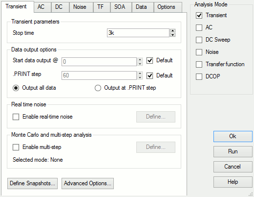
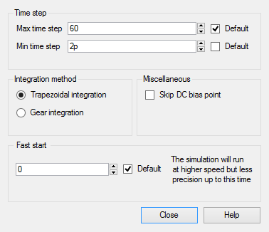
SiMetrix uses your choice of "Stop time" to calculate some of its default settings. Here the stop time figure is relatively high. And one of the resulting default values - the minimum time step - is too high to allow the simulation to run successfully.
You'll find the minimum time step setting - under the "Advanced Options" button. For present purposes - provided it's short enough - the actual choice of minimum step length is not important. So I set a really short two pico-second - effectively removing it as a parameter.
SiMetrix Switches Are Analogue Devices
SiMetrix switches don't simply open and close - like regular switches. Instead - they have both an ON resistance and an OFF resistance. The default OFF (open) resistance is 1 Meg. In order to make them behave more like regular switches - I've increased the OFF resistance to something that more closely resembles an open circuit.

The switches are (by default) normally-open. Since I used them to simulate the relay contacts - I had to convert one (S1) to normally-closed. To create a N/C switch - swap the "On Voltage" and the "Off Voltage".
Why Is The Simulation 5-Volts?
The Cmos Models that come with SiMetrix are designed for a 5-volt supply. So I've had to set up a 5-volt simulation. However - the circuit itself will work at anything from 5v to 15v. You just have to make sure that the coil of your relay - is designed to work at the voltage you want to use.
Download Simulation Files
|