A simple - easy to use - DIY Two-Zone Intruder Alarm System.
Introduction
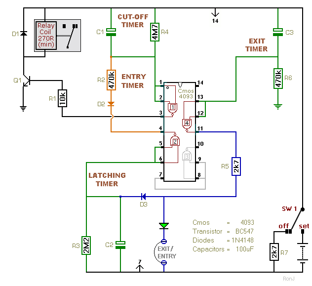
This alarm is basically a sequence of four Simple Timers. The Exit Timer is first. It allows you to leave the building. This is followed by an Indefinite Pause - while the alarm waits for an intruder. When one of the normally-closed trigger switches is opened - Pin 11 will activate the Latching Timer. It prevents the intruder from defeating the alarm - by simply closing the door behind him. The Latching Timer output starts the Entry Timer. It gives a legitimate visitor time to switch the alarm off. And finally - there's the Cut-Off Timer. It stops the noise from becoming a nuisance.
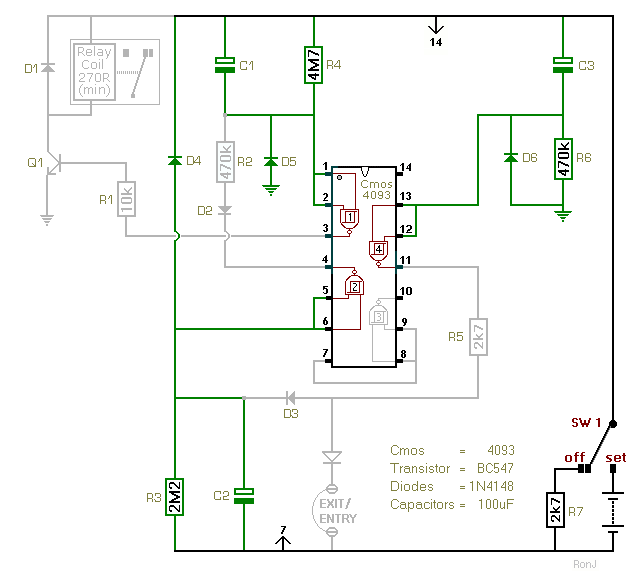
Until the three capacitors are completely discharged - the various timers are not completely reset. When the alarm is switched off - the existing circuit components will provide a number of - more or less satisfactory - discharge paths. And R7 will help - by creating a few more. In normal use - this uncertainty surrounding the precise discharge routes - probably isn't a problem. But an alarm circuit should really operate reliably and predictably - every time. So we're going to improve the design - by providing a dedicated rapid discharge path - for each capacitor.
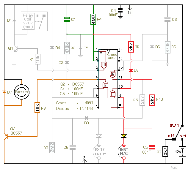
Here we're going to complete the alarm circuit - by adding an entry buzzer - and an instant alarm zone. We'll use a second transistor to sound the buzzer. And the spare inverter will provide the instant zone. The instant zone will bypass the entry delay - and sound the siren immediately.
|


