The alarm is set twice during the simulation. The top line of the graph shows that one minute into the simulation - V2 moves Sw1 to the "set" position. That's when the (blue) exit delay begins. The red line represents the approximate switching point of gate 4. After about 30 seconds - when the blue line drops below the red line - the exit delay ends - the gate 4 output goes high - and the alarm is set.
At 200 seconds - when V3 opens the E/E loop (Sw2) - the buzzer sounds immediately - and the (black) entry delay begins. As before - the red line represents the approximate switching point of gate 1. After about 30 seconds - when the black line drops below the red line - the entry delay ends - and the gate 1 output pin goes high. The high output pin energizes the relay and sounds the siren.
Graphs
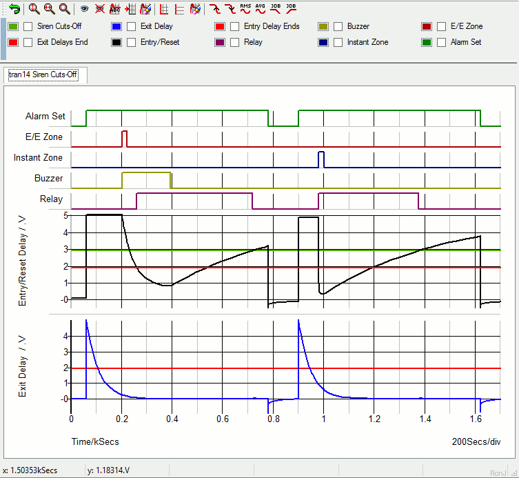
The Cmos 4093 has Schmidt-trigger gates. These gates have two switching points. The red lines represent the point at which a falling voltage takes the input pins low. And the green line represents the point at which a rising voltage takes the pins high. The difference between the two voltages - is the hysteresis of the gates.
While the buzzer is sounding - the black line continues to fall. At about 400 seconds - when the buzzer switches off - the black line starts to climb again. Hysteresis makes it necessary for the black line to climb as far as the green line - before the gate 1 output pin goes low - and the relay de-energizes.
Thirteen minutes into the simulation - V2 switches the alarm off for two minutes - and then switches it on again. Eighty seconds later - V4 activates the instant zone (Sw3). This time there is no entry delay. The black line plunges rapidly below the red line - and the relay energizes immediately. Twenty seconds later Sw3 closes - and the black line starts to climb again slowly. When it crosses the green line - the relay drops-out.
The Sw1 Control Pulse (V2)
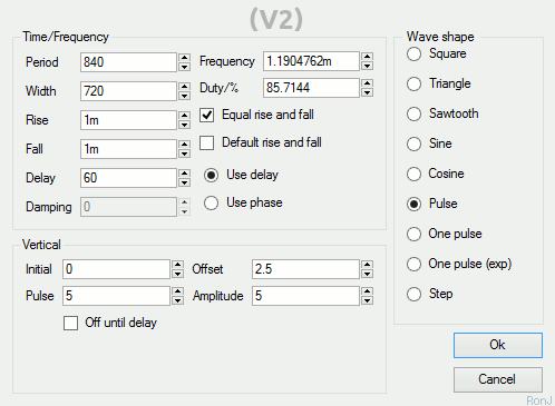
Sw1 is controlled by a waveform generator (V2). After an initial delay of 60 seconds - the generator produces a 5v output pulse that lasts for twelve minutes (720s). This moves Sw1 to the "set" position for the duration of the pulse. When the pulse ends - Sw1 returns to the "off" position. Two-minutes later (840 - 720) V2 repeats the pulse. And Sw1 turns the alarm on for another twelve minutes.
The Sw2 Control Pulse (V3)
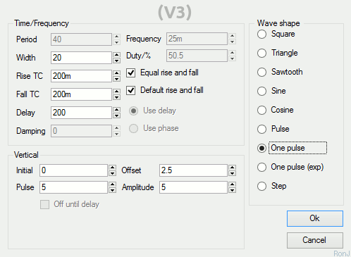
Sw2 is controlled by a waveform generator (V3). After an initial delay of 200 seconds - the generator produces a single 5v output pulse that lasts for 20 seconds. This opens Sw2 for the duration of the pulse - and triggers the E/E zone.
The Sw3 Control Pulse (V4)
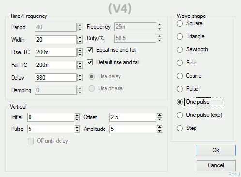
The V4 pulse is delayed for 980 seconds. It doesn't arrive until V2 has armed the alarm for the second time. The single 5v pulse lasts for 20 seconds - and it opens Sw3 for the duration of the pulse. This triggers the Instant Zone.
SiMetrix Switches Are Analogue Devices
SiMetrix switches don't simply open and close - like regular switches. Instead - they have both an ON resistance and an OFF resistance. The default OFF (open) resistance is 1 Meg. In order to make them behave more like regular switches - I've increased the OFF resistance to something that more closely resembles an open circuit.

Note that Sw1 is a two-way switch. It has both normally-open and normally-closed contacts. SiMetrix switches are - by default - normally-open. That is - the "On Voltage" is higher than the "Off Voltage". To create a normally-closed switch - make the "On Voltage" lower than the "Off Voltage".
Analysis Settings
The analysis is straight forward. The "Mode" should be set to "Transient". And the "Stop Time" should be long enough to allow the alarm to complete its two cycles. I set it to 1700 seconds - just under half-an-hour.
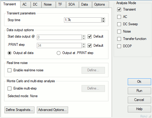
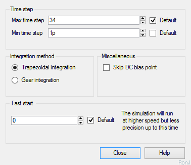
SiMetrix uses your choice of "Stop time" to calculate some of its default settings. Here the stop time figure is relatively high. And one of the resulting default values - the minimum time step - is too high to allow the simulation to run successfully.
You'll find the minimum time step setting - under the "Advanced Options" button. For present purposes - provided it's short enough - the actual choice of minimum step length is not important. So I set a really short one pico-second - effectively removing it as a parameter.
Why Is The Simulation 5-Volts?
The Cmos Models that come with SiMetrix are designed for a 5-volt supply. So - to keep matters simple - I've set up a 5-volt simulation. However - the alarm itself is designed to work over a range of supply voltages. And included in the
Download Material - you'll find both 9v and 12v simulations.
To run these extra simulations successfully - you'll need to install my 9v and 12v Cmos models. This is very easy to do. Simply drag and drop the "MyMods.lb" file - into the small "SiMetrix Command Shell" window. And - when you're asked - confirm that you want to install the new models. Don't Worry! You're not overwriting anything. All the existing models are still there.